User Manual UTC-515/520/532 15.6”, 21.
Copyright The documentation and the software included with this product are copyrighted 2014 by Advantech Co., Ltd. All rights are reserved. Advantech Co., Ltd. reserves the right to make improvements in the products described in this manual at any time without notice. No part of this manual may be reproduced, copied, translated or transmitted in any form or by any means without the prior written permission of Advantech Co., Ltd. Information provided in this manual is intended to be accurate and reliable.
Declaration of Conformity FCC Class A Note! This equipment has been tested and found to comply with the limits for a Class A digital device, pursuant to Part 15 of the FCC Rules. These limits are designed to provide reasonable protection against harmful interference when the equipment is operated in a commercial environment.
Technical Support and Assistance 1. 2. Visit the Advantech website at http://support.advantech.com where you can find the latest information about the product. Contact your distributor, sales representative, or Advantech's customer service center for technical support if you need additional assistance.
Safety Instructions 1. 2. 3. Read these safety instructions carefully. Keep this User Manual for later reference. Disconnect this equipment from any AC outlet before cleaning. Use a damp cloth. Do not use liquid or spray detergents for cleaning. 4. For plug-in equipment, the power outlet socket must be located near the equipment and must be easily accessible. 5. Keep this equipment away from humidity. 6. Put this equipment on a reliable surface during installation.
UTC-515/520/532 User Manual vi
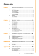
Contents Chapter 1 General Information ............................1 1.1 1.2 Introduction ............................................................................................... 2 Specifications ............................................................................................ 2 1.2.1 UTC-515A/B/C .............................................................................. 2 1.2.2 UTC-515E ..................................................................................... 3 1.2.
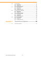
B.2 B.3 B.4 B.5 B.6 UTC-P02 (MSR)...................................................................................... 31 B.2.1 Specifications.............................................................................. 31 B.2.2 Packing List ................................................................................ 31 B.2.3 Ordering Information................................................................... 31 UTC-P03 (RFID Reader) ............................................................
Chapter 1 1 General Information
1.1 Introduction UTC-500 Series products deliver 15.6”, 21.5”, and 32” fanless, low-power, all-in-one touch panel solutions suitable for many applications including control room Industrial PCs, production line industrial digital signage, showroom interactive signage, selfservice kiosks, and public service terminals. They also fulfill much digital retail and hospitality service needs such as in healthcare, vending, education, entertainment and information handling. They are beautiful, durable, and reliable.
Relative Humidity Environmental Vibration Specifications Shock 10 ~ 95% @ 40° C non-condensing 0.5G 5 G peak acceleration (11 msec. duration) EMC/ Safety CE, FCC, UL, CCC CB,BSMI LCD Display IP65/ NEMA4 Compliant Input Rating 12 V/5 A 12 V/5 A (60 W ITE Adapter) (60 W ITE Adapter) Typical 32W Power Consumption Max. 40W Typical 40W Max. 50W Size/Type 15.6" TFT LCD Max. Resolution 1366 x 768 Max. Color 262 K Pixel Pitch (mm) 248.25 (H) x 248.
Windows Embedded 7, Windows Embedded 8, Embedded Linux 3.0 OS Support Environmental Specifications Power Supply Operating Temperature 0 ~ 40 °C (32 ~ 104 °F) Relative Humidity 10 ~ 95% @ 40° C non-condensing Vibration 0.5G Shock 5 G peak acceleration (11 msec. duration) EMC/ Safety CE, FCC, UL, CCC CB,BSMI Front Panel Protection IP65/ NEMA4 Compliant Input Rating 12 V/5 A (60 W ITE Adapter) Typical 40W Power consumption Max.
Intel Atom Dual Intel Core™ i7 3517UE 1.7 GHz Core D2550 1.8 GHz (UTC-520B) (UTC-520C) Chipset T40E + A50M Intel Atom D2550 Intel QM77 + Intel NM10 L2 Cache 512 KB 1 MB 1 MB (L3, 4MB) Memory 1 x SO-DIMM DDR3 1066 MHz up to 4 GB 1 x SO-DIMM DDR3 1066 MHz up to 4 GB 1 x SO-DIMM DDR3/DDR3L 1333/1600 MHz up to 8 GB SSD Support 1 x CFast Support 1 x CFast HDD 1 x 2.
LCD Display Size/Type 21.5" TFT LCD with LED backlight Max. Resolution 1920 x 1080 Max. Color 16.7 M Pixel Pitch (mm) 248.25 (H) x 248.25 (V) Brightness (cd/m2) 250 (Optional 400) View Angle 178°/178° Type Projected Capacitive.
Intel® Core™ i5-4300U (UTC-520E) CPU Intel® Core™ i3-4010U (Available)* Intel® Celeron J1900 (UTC-520D) Intel® Celeron 2980U (Available)* 2 GHz (Quad-Core) Cache L2 Cache 2MB L3 Cache 3MB Memory 1 x SO-DIMM DDR3L 1333 MHz up to 8 GB 1 x SO-DIMM DDR3L 1333 / 1600 MHz up to 8 GB HDD 1 x 2.5 internal SATA HDD bay 1 x 2.5 internal SATA HDD bay Network (LAN) 2 x Gigabit Ethernet ports (Supports Wake on LAN) I/O ports 1.
LCD Display Size/Type 21.5" TFT LCD Max. Resolution 1920 x 1080 Max. Color 16.7M Pixel Pitch (um) 248.25 (H) x 248.25 (V) Brightness (cd/m2) 250 (Optional 400) View Angle 178°/178° Type Projected Capacitive.
AMD® G-Series T40E Dual- Intel Core™ i7 3517UE 1.7 core 1.0 GHz (UTC- 532A) GHz (UTC-532C) Chipset T40E + A50M Intel QM77 L2 Cache 512 KB 1 MB (L3, 4 MB) Memory 1 x SO-DIMM DDR3 1066 up to 4GB 1 x SO-DIMM DDR3/DDR3L 1333/1600 MHz up to 8 GB HDD 1 x 2.5 internal SATA HDD bay Network (LAN) 2 x Gigabit Ethernet ports Processor System I/O Ports 3 x RS-232 COM (RS-422/ 485)* 2 x RS-232 COM (RS-422/ 485)* 4 x USB 2.0 2 x USB 2.0, 2 x USB 3.
1.2.6 UTC-532D/E Intel® Core™ i5-4300U (UTC-532E) CPU Intel® Celeron J1900 (UTC-532D) Intel® Core™ i3-4010U (Available)* Intel® Celeron 2980U (Available)* Processor System Base Frequency 2 GHz (Quad-Core) 1.9 GHz (Dual-Core) Cache 2 MB 3 MB Memory 1 x SO-DIMM DDR3L 1333 1 x SO-DIMM DDR3L 1333 / MHz up to 8 GB 1600 MHz up to 8 GB HDD 1 x 2.5 internal SATA HDD bay Network (LAN) 2 x Gigabit Ethernet ports I/O Ports 2 x RS-232 COM (RS-422/485)* 2 x RS-232 COM (RS-422/485)* 3 x USB 2.
Projected Capacitive Touch Panel (Pcap. Flat Glass) / Glass Panel (No touch function) Light Transmission 90% ± 2% / 90% Controller USB Interface / - 1.3 Dimension Dimensions: 390 x 240 x 45 mm 100 139.91 240.12 100 49.06 VESA Hole M4 depth=5mm 40 45.20 389.81 VESA Mounting: 100 x 100 mm 139.91 49.06 100 100 VESA Hole M4 depth=5mm 11 UTC-515/520/532 User Manual General Information 1.3.
1.3.2 UTC-520 Dimensions: 518 x 314 x 44 mm 395.67 308.82 208.82 101.96 201.96 517.64 73.36 313.51 VESA Hole M4 Depth=5mm 40 43.50 420 517.64 VESA Mounting: 100 x 100 mm 101.96 201.96 395.67 308.82 208.82 73.
Dimensions: 786 x 480 x 63 mm 100 100 VESA Hole M6 depth=10mm 100 480.24 40 62.50 785.64 VESA Mounting: 200 x 200 mm 100 100 VESA Hole M6 depth=10mm 100 100 140.12 292.82 13 UTC-515/520/532 User Manual General Information 100 140.12 292.82 Chapter 1 1.3.
UTC-515/520/532 User Manual 14
Chapter 2 System Setup 2
2.1 Quick Start Tour Before starting to set up the UTC, take a moment to become familiar with the locations and functions of the connectors and features, which are illustrated in the figures below. 2.1.1 Front View LCD panel with Touchscreen options (PE/RE/GE) Note! UTC-515 & UTC-520 PE Model featuring Antimicrobial Corning® Gorilla® Glass for Capacitive Touch Panel. Details please see Appendix C RE (Resistive) option is not available for UTC-532.
Chapter 2 2.1.2 Rear View VESA Mounting Note! Please use only VESA compatible mounting – Detail Floor Stand & wall mount specifications please see Appendix A. I/O Ports SKU variance please refer to Chapter 2.2 for detail. 2.1.3 Side View Side Groove Note! The Side Groove is an unique feature of UTC-500 Series that holds UTC-Peripherals all around the frames with two screws. Please see Chapter 3.6 for detail installation guide.
2.2 I/O Ports 2.2.1 UTC-515 A B C D E F G H I J K M L A. Power Switch B. Antenna Port C. Line-out D. Mic-in E. COM3 (UTC-515A/B only) F. COM2 G. COM1 H. USB 2.0 x 4 (USB 3.0 x 2 for UTC-515C/E) I. HDMI Port J. VGA Port K. LAN Ports x 2 L. CFast Slot (UTC-515A/B only) M. DC input 2.2.2 UTC-520 A B C D E F G H I J L K A. Antenna Port H. HDMI Port B. Line-out I. VGA Port C. Mic-in J. LAN Ports x 2 D. COM3 (UTC-520A/B only) K. CFast Slot (UTC-520A/B only) E. COM2 L. DC Input F. COM1 M.
A B C D E I J K L F. Antenna Port G. Line-out H. Mic-in I. COM3 (UTC-532A only) J. COM2 K.COM1 L. AC input 2.3 Setup Procedures 2.3.1 Power on UTC 1. 2. 3. 4. 5. Connect an adaptor with input voltage rated 12V/5A for all UTC-515 and UTC520A/B/D SKUs. Connect an adaptor with Input voltage rated 12V/7A for UTC-520C/E SKUs. Connect an AC power cable for all UTC-532 SKUs. Be sure always handle the power cords by holding the plugs ends only.
2.3.3 Installing System Software Recent releases of operating systems from major vendors include setup programs that load automatically and guide you through hard disk preparation and operating system installation. Some distributors and system integrators may have already preinstalled system software prior to shipment of your UTC. Note! Installing software or drivers requires an installed storage which is sold separately from standard SKUs as options. 2.3.
Chapter 3 3 Hardware Upgrade & Installation
3.1 Introduction UTC consists of a PC-based computer that is housed in an Aluminum extrusion. You can install a HDD, DRAM, and Compact Flash (A/B platform only) by removing the rear cover. Any maintenance or hardware upgrades can be easily completed after removing the rear cover. Warning! Do not remove the rear cover until you have verified that no power is flowing within the UTC. Power must be switched off and the power cord must be unplugged. 3.2 Installing the 2.5” Storage UTC reserved a 2.
Please follow the CFAST Card assembly as in the following diagram. (Note the direction of the CFAST). Hardware Upgrade & Installation 3.4 Installing the Memory 1. 2. 3. 4. Detach and remove the rear cover. Remove the 4 pcs screws on the Heatsink. Turn to bottom side and remove the 2 pcs screws. Install DRAM in the SO-DIMM socket. 23 Chapter 3 3.
3.5 Installing wireless LAN Card (option) 1. 2. 3. 4. 5. 6. 7. Detach and remove the rear cover. Remove the 4 pcs screws on the heatsink. Install WLAN card onto MiniPCIe Slot on the M/B bottom side. Connect coaxial cable to ANT1 and ANT2 on WLAN card. Finish antenna bracket/washer/nuts installation inside chassis. Reassemble the back cover. Install the antenna on SMA connector on chassis exterior.
Appendix A Installation Accessories A
A.1 Introduction The UTC-500 Series Floor Stand & Wall Mount blends simplicity with style. It makes optimal use of space, and its compact design saves money in shipping fees. UTC500 Series is elegantly designed to fit many different customer scenarios, from kiosks to reception areas. The slim and stylish unit is easy to store, easy to ship and easy to set up. Installation is simple; it can be done in about ten minutes and the finished result makes an attractive, one-piece solution. A.
27 VESA 75/100 mm 79 .5 75 100 115 78 70 .5 Firmly fix to a solid wall Weight capacity up to 20 kg Material: Steel Sits: 27 mm from the wall For UTC-515/520 A.
UTC-H01-STANDE H-shape floor stand 510 558.
Appendix B UTC Peripherals B
B.1 UTC-P01 (Camera Module) B.1.1 Specifications Interface USB (Cable Length:50cm) Image Resolution 2592 (H) x 1944 (V) Focusing Range 10 cm~ ∞; Supports auto focus 640 x 480 @ 30 fps max Frame Rate 1280 x 1024 @ 30 fps max 1600 x 1200 @ 15 fps max 2592 x 1944 @ 15 fps max Video Format MJPG OS Support Windows XP/7/8 Dimensions 130 x 35 x 40 mm Operating Temperature 0 ~ 40° C B.1.2 Packing List Description Quantity Cable Clamp 2 Camera Module Unit 1 B.1.
Appendix B UTC Peripherals B.2 UTC-P02 (MSR) B.2.1 Specifications Interface USB (Cable Length:50cm) TRACK 1 / IATA / 210 bpi / 79 Alphanumeric Characters Track Configuration TRACK 2 / ABA / 75 bpi / 40 Numeric Characters TRACK 3 / Thrift / 210 bpi / 107 Numeric Characters Card Standard ANSI, ISO, and ABA.
B.3 UTC-P03 (RFID Reader) B.3.1 Specifications Interface USB (Cable Length:50cm) Frequency 13.
Description Quantity Cable Clamp 2 RFID Reader Unit 1 Appendix B UTC Peripherals B.3.2 Packing List B.3.
B.4 UTC-P06 (Smart Card Reader) B.4.1 Specifications Interface USB (Cable Length:50cm) Card Acceptor/ Reliability User card Friction Type (ID-1) , 200,000 cycles Card Reader LED CPU card -Complies with ISO7816-1,2,3,T=1 and T=0 protocol Memory card -Synchronous 2-line, 3-line and I2C interface Dual color LED indicator Complies with PC/SC version 1.0 standards OS Support Windows XP/ 7 Dimensions 130 x 35 x 40 mm Operating Temperature 0 ~ 40 °C B.4.
B.5.1 Specifications Interface Scanning Performance USB (Cable Length:50cm) Scan Rate: 2D mode: 53 images/s Scan angle: 40° (Horizontal), 26° (Vertical) Optical resolution: 752 (H) x 480 (V) pixels, 256 gray levels Symbology Typical Reading Distances Standard Code 39 UPC/EAN Data Matrix PDF 417 Density Min. Dist. Max. Dist. 0.125 mm/5 mils 4 .7 cm/1.8" 17.7 cm/7.0" 0.25 mm/10 mils 1.7 cm/0.7" 33.2 cm/13.1" 0.33 mm/13 mils 2.5 cm /1.0 " 41.9 cm/16.5" 0.254 mm/10 mils 2.7 cm /1.0" 17.1 cm/6.
B.5.2 Packing List Description Quantity Cable Clamp 2 Barcode Reader Unit 1 B.5.
B.6.1 Specifications 13.56MHz frequency RFID Read mode: ISO 15693/14443A/B/18000-3/Felica Reading range: 3 +/- 1cm 2D mode scan rate: 56 images 2D Barcode Reader Linear emulation scan rate: 200 images/sec Optical resolution: 752x480 pixels, 256 gray levels User card friction type (ID-1), 200,000 cycles Smart Card reader SAM card: 5000 insertion Compliant CPU card and memory card Magnetic Stripe Card Reader Card Standard ANSI, ISO, and ABA.
UTC-515/520/532 User Manual 38
Appendix C C Touch Screen Options
C.
Appendix C Touch Screen Options UTC-515/520/532 User Manual 41
www.advantech.com Please verify specifications before quoting. This guide is intended for reference purposes only. All product specifications are subject to change without notice. No part of this publication may be reproduced in any form or by any means, electronic, photocopying, recording or otherwise, without prior written permission of the publisher. All brand and product names are trademarks or registered trademarks of their respective companies. © Advantech Co., Ltd.
43 XXX-XXXX User Manual