User Manual UTC-520A/B AMD T40E (UTC-520A) & Intel Atom D2550 (UTC-520B) Processor- based Ubiquitous 21.
Copyright The documentation and the software included with this product are copyrighted 2010 by Advantech Co., Ltd. All rights are reserved. Advantech Co., Ltd. reserves the right to make improvements in the products described in this manual at any time without notice. No part of this manual may be reproduced, copied, translated or transmitted in any form or by any means without the prior written permission of Advantech Co., Ltd. Information provided in this manual is intended to be accurate and reliable.
Declaration of Conformity FCC Class A Note: This equipment has been tested and found to comply with the limits for a Class B digital device, pursuant to part 15 of the FCC Rules. These limits are designed to provide reasonable protection against harmful interference in a residential installation. This equipment generates, uses and can radiate radio frequency energy and, if not installed and used in accordance with the instructions, may cause harmful interference to radio communications.
Technical Support and Assistance 1. 2. Visit the Advantech web site at http://support.advantech.com where you can find the latest information about the product. Contact your distributor, sales representative, or Advantech's customer service center for technical support if you need additional assistance.
Safety Instructions 1. 2. 3. Read these safety instructions carefully. Keep this User Manual for later reference. Disconnect this equipment from any AC outlet before cleaning. Use a damp cloth. Do not use liquid or spray detergents for cleaning. 4. For plug-in equipment, the power outlet socket must be located near the equipment and must be easily accessible. 5. Keep this equipment away from humidity. 6. Put this equipment on a reliable surface during installation.
UTC-520A/B User Manual vi
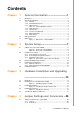
Contents Chapter 1 General Information ............................1 1.1 1.2 Introduction ............................................................................................... 2 General Specifications .............................................................................. 2 1.2.1 General ......................................................................................... 2 1.2.2 Standard PC functions .................................................................. 2 1.2.
Table 4.1: Connectors ............................................................... 28 Mechanical.................................................................................. 29 Figure 4.1 Jumper and Connector Layout (Component Side)... 29 Figure 4.2 Jumper and Connector Layout (Solder Side) ........... 30 Jumpers and Connectors (UTC-520B) ................................................... 31 4.2.1 Jumpers ......................................................................................
Chapter 1 1 General Information This chapter gives background information on the UTC-520A/B.
1.1 Introduction The UTC-520A/B is an Intel low-power AMD T40E &Intel Atom D2550 processor computer that is designed to serve as a interactive self-service terminal and as a multimedia computer. It is a PC-based system with 21.5" TFT LCD display, on-board PCIe Ethernet controller, 3 COM port and 1 VGA connector. With a built in internal IDE connector (for CF card), one SATA connector for HDD and an mini PCIe expansion socket, the UTC-520A/B is a compact and user-friendly multi-function computer.
1.2.3 VGA Interface Chipset: The GPU Contains a refresh of the third generation graphics core Memory Size: Up to 512 MB of dynamic video memory allocation Interface: VGA Display mode: – CRT: Analog RGB display output resolution up to 2048*1536 @ 60 Hz UTC-520A UTC-520B DirectX® 11 graphics with UVD 3.0 Up to 2 Display Port/TMDS Integrated VGA DAC Displayport 1.1a Integrated Graphics Engine clock speed: 500 MHz or 280 MHz, dependent DirectX® 9 and OpenGL 3.0 Display Port 1.1, HDMI 1.
Touchscreen: Analog Resistive, Projective Capacitive Power cord: 1702002600 ( US) 1702002605 (Europe) Wireless LAN Module: UTC-520AB-WIFIE UTC-520AB Wireless LAN module Peripherals for UTC-500 series UTC-P01-A0E ( 2M Wecam) UTC-P02-A0E (MSR) UTC-P03-A0E (RFID) UTC-P06-A0E (Smart Card Reader) UTC-P07-A0E (Barcode reader) Standard Floor Stand Kits UTC-K01-STANDE UTC-K02-STANDE UTC-R01-STANDE 1.2.
Chapter 1 1.4 Dimensions 395.67 308.82 208.82 73.36 313.51 VESA Hole M4 Depth=5mm 40 420 43.50 517.64 Figure 1.1 Dimensions of UTC-520A/B 5 UTC-520A/B User Manual General Information 101.96 201.96 517.
UTC-520A/B User Manual 6
Chapter 2 2 System Setup This chapter details system setup on the UTC-520A/B.
2.1 A Quick Tour of the UTC-520A/B Before you start to set up the UTC-520A/B, take a moment to become familiar with the locations and purposes of the controls, drives, connectors and ports, which are illustrated in the figures below. When you place the UTC-520A/B upright on the desktop, its front panel appears as shown in Figure 2.1. Figure 2.1 Front view of UTC-520A/B When you turn the UTC-520A/B around and look at its rear cover, you will find the I/O section as shown in Fig. 2.2.
D E F G H I J L M K System Setup A. Antenna Port B. Line-out C. Min-in D. COM3 E. COM2 F. COM1 G. USB 2.0 x 4 H. HDMI I. VGA J. LAN Ports x 2 K. CFast L. DC Input M. Power switch 2.2 Installation Procedures 2.2.1 Connecting the Power Cord The UTC-520A/B can be powered by a DC electrical outlet. Be sure to always handle the power cords by holding the plug ends only. Please follow the Figure 2.5 to connect the male plug of the power cord to the DC inlet of the UTC-520A/B. 2.2.
2.3 Running the BIOS Setup Program Your UTC-520A/B is likely to have been properly set up and configured by your dealer prior to delivery. You may still find it necessary to use the UTC-520A/B's BIOS (Basic Input-Output System) setup program to change system configuration information, such as the current date and time or your type of hard drive. The setup program is stored in read-only memory (ROM).
After installing your system software, you will be able to set up the Ethernet, XGA, audio, and touchscreen functions. All drivers are stored in a CD-ROM disc entitled “Drivers and Utilities” which can be found in your accessory box. The various drivers and utilities in the CD-ROM disc have their own text files which helps users install the drivers and understand their functions. These files are a very useful supplement to the information in this manual.
UTC-520A/B User Manual 12
Chapter 3 3 Hardware Installation and Upgrading This chapter details installing the UTC-520A/B hardware. Sections include: Introduction Installing the 2.
3.1 Introduction The UTC-520A/B consists of a PC-based computer that is housed in an Aluminum extrusion. You can install a HDD, DRAM, and Compact Flash by removing the rear cover. Any maintenance or hardware upgrades can be easily completed after removing the rear cover. Warning! Do not remove the rear cover until you have verified that no power is flowing within the UTC-520A/B. Power must be switched off and the power cord must be unplugged.
1. Please follow the CFAST Card assembly as in the following diagram. (Please notice the direction of the CFAST) 3.4 Installing the Memory 1. 2. 3. 4. Detach and remove the rear cover. Remove the 4 pcs screws on the Heatsink. Turn to bottom side and remove the 2 pcs screws. Install DRAM in the SO-DIMM socket. Figure 3.3 Installing the memory 15 UTC-520 User Manual Hardware Installation and Upgrading Figure 3.2 Installing the Compact Flash card Chapter 3 3.
3.5 Installing the Wireless LAN Card 1. Remove 21 pcs screws of back cover. 2. Remove cable connectors on M/B top side.
Remove 2 pcs screws on VGA connector. Chapter 3 3. Hardware Installation and Upgrading Remove 4 pcs screws on M/B heatsink.
4. Remove cable connectors on M/B bottom side. 5. Install the WLAN card on mini PCI-e slot (M/B bottom side).
Put the M/B back and Ass'y back the cables on M/B bottom side. UTC-520A COM1/2 Cable pin1 On UTC-520A 19 COM3 Cable pin 1 UTC-520 User Manual Hardware Installation and Upgrading 6.
UTC-520B COM3 Cable pin1 On UTC-520B COM1/2 Cable pin1 on UTC-520B 7. Ass'y back the cables on M/B top side. Ass'y back the 4 pcs screws on M/B heatsink. Ass'y back the 2 pcs screws on VGA connector. 8. Coaxial cable & bracket.
Chapter 3 Put the black rubber gasket in SMA side first Hardware Installation and Upgrading Put the bracket on SMA connector 21 UTC-520 User Manual
Install the Washer & Nut then turning tight. 9.
Chapter 3 10. Remove the back cover "Hole cover" by Slotted Screwdriver. Hardware Installation and Upgrading 11. Ass'y back the 21 pcs screws of back cover.
12.
Chapter 4 4 Jumper Settings and Connectors This chapter tells how to set up the UTC-520A/B hardware, including instructions on setting jumpers and connecting peripherals, switches and indicators. Be sure to read all the safety precautions before you begin the installation procedures.
4.1 Jumpers and Connectors (UTC-520A) 4.1.1 Jumpers 4.1.1.1 Jumper List J1 Clear CMOS J2 Auto Power On Setting J3 LCD Power J5 COM2 Setting 4.1.1.2 Jumper Settings J1 Clear CMOS Part Number 1653003101 Footprint HD_3x1P_79_D Description PIN HEADER 3x1P 2.0mm 180D(M) DIP 2000-13 WS Setting Function (1-2)* Normal (2-3) Clear COMS J2 Auto Power On Setting Part Number 1653002101 Footprint HD_2x1P_79_D Description PIN HEADER 2*1P 180D(M)SQUARE 2.
Chapter 4 +12V J5 COM2 Setting Part Number 1653003260 Footprint HD_3x2P_79 Description PIN HEADER 3x2P 2.0mm 180D(M) SMD 21N22050 Setting Function (1-2)* RS232 (3-4) RS485 (5-6) RS422 4.1.1.3 Jumper Description Cards can be configured by setting jumpers. A jumper is a metal bridge used to close an electric circuit. It consists of two metal pins and a small metal clip (often protected by a plastic cover) that slides over the pins to connect them.
4.1.2 Connectors 4.1.2.1 Connector List Table 4.
Chapter 4 4.1.3 Mechanical 4.1.3.1 Jumper and Connector Location Jumper Settings and Connectors Figure 4.
CN24 CN8 J5 CN25 Audio GPIO J5 COM 1/2 COM 3/4 CN26 CN28 CN29 CN31 BIOS MIOe PCIe Mini card CFast Socket Figure 4.
4.2.1 Jumpers 4.2.1.1 Jumper List Table 4.2: Jumpers Function J2 48-bit LVDS2 Power J3 Auto Power on setting J4 COM2 Setting J6 Clear CMOS 4.2.1.2 Jumper Settings J2 48 bits LVDS2 Power Part Number 1653003260 Footprint HD_3x2P_79 Description PIN HEADER 3x2P 2.0mm 180D(M) SMD 21N22050 Setting Function (1-3) +3.3V (3-5)* +5V (3-4) +12V J3 Auto Power On Setting Part Number 1653002101 Footprint HD_2x1P_79_D Description PIN HEADER 2*1P 180D(M)SQUARE 2.
(1-2)* RS232 (3-4) RS485 (5-6) RS422 J6 Clear CMOS Part Number 1653003101 Footprint HD_3x1P_79_D Description PIN HEADER 3x1P 2.0mm 180D(M) DIP 2000-13 WS Setting Function (1-2)* Normal (2-3) Clear COMS 4.2.1.3 Jumper Description Cards can be configured by setting jumpers. A jumper is a metal bridge used to close an electric circuit. It consists of two metal pins and a small metal clip (often protected by a plastic cover) that slides over the pins to connect them.
Chapter 4 4.2.2 Connectors 4.2.2.1 Connector List Table 4.
4.2.3 Mechanical 4.2.3.1 Jumper and Connector Location y &1 &1 p &1 - &1 &1 &1 & 1 &1 - & 1 &1 & 1 - - &1 &1 &1 &1 &1 &1 &1 & 1 +'' 3: 5 /(' Figure 4.3 Jumper and Connector Layout (Component Side) CN11 CN12 CN31 CN19 CN24 J4 J5 CN13 CN30 Figure 4.
Appendix A A Pin Assignments
A.1 Pin Assignments (UTC-520A) CN1 Power Switch Part Number 1655302020 Footprint WF_2P_79_BOX_R1_D Description WAFER BOX 2P 2.0mm 180D(M) DIP A2001WV2-2P Pin Pin Name 1 PSIN 2 GND CN2 Inverter Power Output Part Number 1655000453 Footprint WHL5V-2M-24W1140 Description WAFER BOX 2.
SATA Power Part Number 1655001154 Footprint WF_4P_98_BOX_R1_D Description WAFER BOX 4P 2.50mm 180D(M) DIP 24W1170-04S10-01 Pin Pin Name 1 +5V 2 GND 3 GND 4 +12V CN6 SATA 2 Part Number 1654007578 Footprint SATA_7P_WATF-07DBN6SB1U Description Serial ATA 7P 1.
CN7 RS422/485 Part Number 1655304032 Footprint WF_5P_49_BOX_85205 Description WAFER 5P 1.25mm 180D(M) SMD 85205-05701 Pin Pin Name 1 422RX- 2 422RX+ 3 422/485TX+ 4 422/485TX- 5 GND CN8 GPIO Part Number 1653004099 Footprint HD_5x2P_79_23N685B-10M10 Description BOX HEADER 5x2P 2.
DDR3 SODIMM Socket Part Number 1651001648 Footprint DDR3_204P_2-2013311-1 Description DDR3 SODIMM H=9.
CN12 Internal USB Part Number 1653005260 Footprint HD_5x2P_79_N10 Description PIN HEADER 2x5P 2.0mm 180D(M) SMD 21N22050 Pin Pin Name 1 +5V 2 +5V 3 A_D- 4 B_D- 5 A_D+ 6 B_D+ 7 GND 8 GND 9 GND CN13 SMBus Part Number 1655904020 Footprint FPC4V-125M Description WAFER 4P 1.
LAN Part Number 1652003274 Footprint RJ45_28P_RTB-19GB9J1A Description PHONE JACK RJ45 28P DIP RTB-19GB9J1A Pin Pin Name 1 TX+(10/100),BI_DA+(GHz) 2 TX-(10/100),BI_DA-(GHz) 3 RX+(10/100),BI_DB+(GHz) 4 BI_DC+(GHz) 5 BI_DC-(GHz) 6 RX-(10/100),BI_DB-(GHz) 7 BI_DD+(GHz) 8 BI_DD-(GHz) CN17 48 bits LVDS Panel Part Number 1653920200 Footprint SPH20X2 Description B/B Conn. 40P 1.25mm 90D SMD DF13-40DP-1.25V Pin Pin Name 1 +3.3V, +5V or +12V 2 +3.
20 LVDS1_D2- 21 LVDS0_D2+ 22 LVDS1_D2+ 23 GND 24 GND 25 LVDS0_CLK- 26 LVDS1_CLK- 27 LVDS0_CLK+ 28 LVDS1_CLK+ 29 GND 30 GND 31 NC 32 NC 33 GND 34 GND 35 LVDS0_D3- 36 LVDS1_D3- 37 LVDS0_D3+ 38 LVDS1_D3+ 39 NC 40 NC UTC-520A/B User Manual 42
External USB Part Number 1654009513 Footprint USB_8P_UB1112C-8FDE-4F Appendix A Pin Assignments CN18 Description Pin Pin Name 1 +5V 2 D- 3 D+ 4 GND CN19 External USB Part Number 1654009513 Footprint USB_8P_UB1112C-8FDE-4F Description Pin Pin Name 1 +5V 2 D- 3 D+ 4 GND 43 UTC-520A/B User Manual
CN20 HDMI Part Number 1654009225 Footprint HDMI_19P_QJ51193-FFD4-7F Description HDMI Conn 19P 0.
12V Power Input Part Number 1655404090 Footprint WF_2x2P_165_BOX_RA_D_740SP Description ATX PWR CONN. 2x2P 4.2mm 180D(M) DIP 24W4310-04S Pin Pin Name 1 GND 2 GND 3 +12V 4 +12V CN23 VGA Part Number 1654000055 Footprint DBVGA-VF5MS Description D-SUB Conn.
CN24 Audio Part Number 1653004099 Footprint HD_5x2P_79_23N685B-10M10 Description BOX HEADER 5x2P 2.
GND 20 GND CN26 COM3/COM4 Part Number 1653004793 Footprint HD_10x2P_79_23N685B-20M10 Appendix A Pin Assignments 19 Description Pin Pin Name 1 DCD3# 2 DSR3# 3 RXD3 4 RTS3# 5 TXD3 6 CTS3# 7 DTR3# 8 RI3# 9 GND 10 GND 11 DCD4# 12 DSR4# 13 RXD4 14 RTS4# 15 TXD4 16 CTS4# 17 DTR4# 18 RI4# 19 GND 20 GND 47 UTC-520A/B User Manual
CN28 MIOe Part Number 1654006235 Footprint BB_40x2P_32_1625x285_2HOLD Description Pin Pin Name 1 GND 2 GND 3 PCIE_RX0+ 4 PCIE_TX0+ 5 PCIE_RX0- 6 PCIE_TX0- 7 GND 8 GND 9 PCIE_RX1+ 10 PCIE_TX1+ 11 PCIE_RX1- 12 PCIE_TX1- 13 GND 14 GND 15 PCIE_RX2+ 16 PCIE_TX2+ 17 PCIE_RX2- 18 PCIE_TX2- 19 GND 20 GND 21 PCIE_RX3+ 22 PCIE_TX3+ 23 PCIE_RX3- 24 PCIE_TX3- 25 GND 26 GND 27 PCIE_CLK+ 28 LOUTL 29 PCIE_CLK- 30 LOUTR 31 GND 32 AGND 33 SMB_CLK 34
CLK33M 43 SLP_S5# 44 LPC_AD0 45 DDP_HPD 46 LPC_AD1 47 GND 48 LPC_AD2 Appendix A Pin Assignments 42 49 DDP_AUX+ 50 LPC_AD3 51 DDP_AUX- 52 LPC_DRQ#0 53 GND 54 LPC_SERIRQ 55 DDP_D0+ 56 LPC_FRAME# 57 DDP_D0- 58 GND 59 GND 60 USB0_D+ 61 DDP_D1+ 62 USB0_D- 63 DDP_D1- 64 GND 65 GND 66 USB1_D+/USB_SSTX+ 67 DDP_D2+ 68 USB1_D-/USB_SSTX- 69 DDP_D2- 70 GND 71 GND 72 USB2_D+/USB_SSRX+ 73 DDP_D3+ 74 USB2_D-/USB_SSRX- 75 DDP_D3- 76 GND 77 GND 78 USB
UTC-520A/B User Manual 50
PCIe Mini Card Holder Part Number 1654002539 Footprint FOX_AS0B226-S68K7F_HOLDER Description MINI PCI Express 52P 6.8mm 90D SMD AS0B226-S68K7 Pin Pin Name 1 GND 2 GND 3 GND 4 GND 5 NC 6 NC CN30 PCIe Mini Card Part Number 1654002538 Footprint FOX_AS0B226-S68K7F Description MINI PCI Express 52P 6.8mm 90D SMD AS0B226-S68N7 Pin Pin Name 1 WAKE# 2 +3.3VSB 3 NC 4 GND 5 NC 6 +1.
14 NC 15 GND 16 NC 17 NC 18 GND 19 NC 20 NC 21 GND 22 PERST# 23 PERn0 24 +3.3VSB 25 PERp0 26 GND 27 GND 28 +1.5V 29 GND 30 SMB_CLK 31 PETn0 32 SMB_DAT 33 PETp0 34 GND 35 GND 36 USB D- 37 GND 38 USB D+ 39 +3.3VSB 40 GND 41 +3.3VSB 42 NC 43 GND 44 NC 45 NC 46 NC 47 NC 48 +1.5V 49 NC 50 GND 51 NC 52 +3.
Appendix A Pin Assignments UTC-520A/B User Manual 53
CN31 CFast Part Number 1653004402 Footprint CFAST_24P_N7E24 Description CFast 24P 1.27mm 90D(M) SMD N7E24-M516RA-50 Pin Pin Name PC1 CDI PC2 GND PC3 NC PC4 NC PC5 NC PC6 NC PC7 GND PC8 NC PC9 NC PC10 NC PC11 NC PC12 NC PC13 +3.3V PC14 +3.
CN2 DC JACK Part Number 1652005624 Footprint PJ_2P_2DC-G213B200 Description DC POWER JACK 2.5mm 90D(M) DIP 2DC-G213B200 Pin Pin Name 1 +VIN 2 GND CN3 SODIMMDDR3RVS_204 Part Number 1651001648 Footprint DDR3_204P_2-2013311-1 Description DDR3 SODIMM H=9.2mm 204P SMD 2-2013311-1 Pin Pin Name CN5 Power Switch Part Number 1655302020 Footprint WF_2P_79_BOX_R1_D Description WAFER BOX 2P 2.
7 GPIO2 8 GPIO7 9 GPIO3 10 GND CN10 VGA Part Number 1654000055 Footprint DBVGA-VF5MS Description D-SUB Conn. 15P 90D(F) DIP 070242FR015S200ZU Pin Pin Name 1 RED 2 GREEN 3 BLUE 4 NC 5 GND 6 GND 7 GND 8 GND 9 NC 10 GND 11 NC 12 DDAT 13 HSYNC 14 VSYNC 15 DCLK CN11 CFast Part Number 1653004849 Footprint CFAST_24P_N7G24 Description CFast 24P 1.
NC PC4 NC PC5 NC PC6 NC PC7 GND PC8 NC PC9 NC PC10 NC PC11 NC PC12 NC PC13 +3.3V PC14 +3.
CN13 Mini PCIE Part Number 1654006715 Footprint MINIPCI_52P_88911-5204M Description Pin Pin Name 1 WAKE# 2 +3.3VSB 3 NC 4 GND 5 NC 6 +1.5V 7 NC 8 NC 9 GND 10 NC 11 REFCLK- 12 NC 13 REFCLK+ 14 NC 15 GND 16 NC 17 NC 18 GND 19 NC 20 NC 21 GND 22 PERST# 23 PERn0 24 +3.3VSB 25 PERp0 26 GND 27 GND 28 +1.
USB D- 37 GND 38 USB D+ 39 +3.3VSB 40 GND 41 +3.3VSB 42 NC 43 GND 44 NC 45 NC 46 NC 47 NC 48 +1.5V 49 NC 50 GND 51 NC 52 +3.
CN14 SATA Part Number 1654004118 Footprint SATA_7P_50_WATA-07DPLH4U Description Serial ATA 7P 1.27mm 90D(M) SMD WATA-07DPLH4U Pin Pin Name 1 GND 2 TX+ 3 TX- 4 GND 5 RX- 6 RX+ 7 GND CN15 SATA Power Part Number 1655001154 Footprint WF_4P_98_BOX_R1_D Description WAFER BOX 4P 2.
USB3/4 Part Number 1654009513 Footprint USB_8P_UB1112C-8FDE-4F Description USB CONN. 8P 2.0mm 90D DIP UB1112C-8FDE-4F Pin Pin Name 1 +5V 2 D- 3 D+ 4 GND CN17 Internal USB Part Number 1653005260 Footprint HD_5x2P_79_N10 Description PIN HEADER 2x5P 2.
CN18 USB 1/2 Part Number 1654009513 Footprint USB_8P_UB1112C-8FDE-4F Description USB CONN. 8P 2.0mm 90D DIP UB1112C-8FDE-4F Pin Pin Name 1 +5V 2 D- 3 D+ 4 GND CN19 COM1/COM2 RS-232 Part Number 1653004793 Footprint HD_10x2P_79_23N685B-20M10 Description BOX HEADER 10x2P 2.
CN20 RS422/485 1 Part Number 1655304032 Footprint WF_5P_49_BOX_85205 Description WAFER 5P 1.
CN22 RS422/485 2 Part Number 1655304032 Footprint WF_5P_49_BOX_85205 Description WAFER 5P 1.25mm 180D(M) SMD 85205-05701 Pin Pin Name 1 422RX- 2 422RX+ 3 422/485TX+ 4 422/485TX- 5 GND CN24 COM3/COM4 RS-232 Part Number 1653004793 Footprint HD_10x2P_79_23N685B-20M10 Description BOX HEADER 10x2P 2.
GND Matching Cable: 1701200220 CN25 SMBus Part Number 1655904020 Footprint FPC4V-125M Description WAFER 4P 1.
CN14 LAN Part Number 1652003274 Footprint RJ45_28P_RTB-19GB9J1A Description PHONE JACK RJ45 28P DIP RTB-19GB9J1A Pin Pin Name 1 TX+(10/100), BI_DA+(GHz) 2 TX-(10/100), BI_DA-(GHz) 3 RX+(10/100), BI_DB+(GHz) 4 BI_DC+(GHz) 5 BI_DC-(GHz) 6 RX-(10/100), BI_DB-(GHz) 7 BI_DD+(GHz) 8 BI_DD-(GHz) CN30 Audio Part Number 1653004099 Footprint HD_5x2P_79_23N685B-10M10 Description BOX HEADER 5x2P 2.
48 bits LVDS2 Inverter Power Part Number 1655000453 Footprint WHL5V-2M-24W1140 Description WAFER BOX 2.0mm 5P 180D(M) DIP WO/Pb JIH VEI Pin Pin Name 1 +12V 2 GND 3 ENABKL 4 VBR 5 +5V CN35 48 bits LVDS2 Panel Part Number 1653920200 Footprint SPH20X2 Description B/B Conn. 40P 1.25mm 90D SMD DF13-40DP-1.25V(91) Pin Pin Name 1 +5V or +3.3V 2 +5V or +3.3V 3 GND 4 GND 5 +5V or +3.3V 6 +5V or +3.
25 LVDS0_CLK- 26 LVDS1_CLK- 27 LVDS0_CLK+ 28 LVDS1_CLK+ 29 GND 30 GND 31 NC 32 NC 33 GND 34 GND 35 LVDS0_D3- 36 LVDS1_D3- 37 LVDS0_D3+ 38 LVDS1_D3+ 39 NC 40 NC CN36 HDMI Part Number 1654009225 Footprint HDMI_19P_QJ51193-FFD4-7F Description HDMI Conn 19P 0.
eDP Part Number 1653910261 Footprint SPH10X2 Description B/B Conn 10x2P 1.25mm 180D(M)SMD DF13-20DP-1.25V Pin Pin Name 1 GND 2 GND 3 D0- 4 D3- 5 D0+ 6 D3+ 7 GND 8 NC 9 D1- 10 GND 11 D1+ 12 SDAT 13 GND 14 SCLK 15 D2- 16 GND 17 D2+ 18 Hot Plug Detect 19 +5V or +3.3V 20 +5V or +3.
CN38 24 bits LVDS1 Inverter Power Part Number 1655000453 Footprint WHL5V-2M-24W1140 Description WAFER BOX 2.
Appendix B B UTC-500 Peripherals Series Installation Guide
B.1 UTC-500 Peripherals Series Installation Guide Model UTC-P01-A0E UTC-P02-A0E UTC-P03-A0E UTC-P06-A0E Description 2M Camera Module for UTC-500 Series Magnetic Stripe Card Reader for UTC-500 Series RFID Reader for UTC-500 Series Smart Card Reader for UTC-500 Series Packing List UTC-PXX CD-Driver Cable Clamp x 2 Assemble the UTC-Peripherals 1. Attach the UTC-peripheral to the UTC 500 series side groove.
Fasten the 2 screws to fix the peripheral in place. 3. Connect the cable to an I/O port (USB). 4. Choose a location to put the cable clamp and attach the cable to it. Attaching a peripheral on the top of the unit 73 UTC-520A/B User Manual Appendix B UTC-500 Peripherals Series Installation Guide 2.
Attaching a peripheral on the bottom of the unit An attachment to the left side UTC-520A/B User Manual 74
Appendix B UTC-500 Peripherals Series Installation Guide UTC-520A/B User Manual 75
www.advantech.com Please verify specifications before quoting. This guide is intended for reference purposes only. All product specifications are subject to change without notice. No part of this publication may be reproduced in any form or by any means, electronic, photocopying, recording or otherwise, without prior written permission of the publisher. All brand and product names are trademarks or registered trademarks of their respective companies. © Advantech Co., Ltd.
77 XXX-XXXX User Manual