UNO-3072L Celeron M/ Pentium M Embedded Automation Computer with Two PCI-Slot Extensions User Manual i
Copyright This document is copyrighted, © 2007. All rights are reserved. The original manufacturer reserves the right to make improvements to the products described in this manual at any time without notice. No part of this manual may be reproduced, copied, translated or transmitted in any form or by any means without the prior written permission of the original manufacturer. Information provided in this manual is intended to be accurate and reliable.
Product Warranty (2 years) Advantech warrants to you, the original purchaser, that each of its products will be free from defects in materials and workmanship for two years from the date of purchase. This warranty does not apply to any products which have been repaired or altered by persons other than repair personnel authorized by Advantech, or which have been subject to misuse, abuse, accident or improper installation.
Declaration of Conformity CE This product has passed the CE test for environmental specifications when shielded cables are used for external wiring. We recommend the use of shielded cables. This kind of cable is available from Advantech. Please contact your local supplier for ordering information. FCC Class A Note: This equipment has been tested and found to comply with the limits for a Class A digital device, pursuant to part 15 of the FCC Rules.
Safety Instructions 1. Read these safety instructions carefully. 2. Keep this user manual for later reference. 3. Disconnect this equipment from DC outlet before cleaning. Do not use liquid or spray detergents for cleaning. 4. For pluggable equipment, the power outlet shall be installed near the equipment and shall be easily accessible. 5. Keep this equipment away from humidity. 6. Put this equipment on a reliable surface during installation. Dropping it or letting it fall could cause damage. 7.
recommended by the manufacture. Discard used batteries according to the manufacturer’s instructions. 14. This device complies with Part 15 of the FCC rules. Operation is subject to the following two conditions: (1) this device may not cause harmful interference, and (2) this device must accept any interference received, including interference that may cause undesired operation. 15. CAUTION: Always completely disconnect the power cord from your chassis whenever you work with the hardware.
Contents Chapter 1 Overview .......................................................... 2 1.1 1.2 1.3 1.4 1.5 Chapter Introduction ....................................................................... 2 Hardware Specifications ................................................... 5 Safety Precautions ............................................................. 7 Chassis Dimensions........................................................... 8 Packing List....................................................
2.8 2.9 2.10 2.11 2.12 2.13 Chapter Power Input ..................................................................... 29 LED and Buzzer for System Diagnosis........................... 31 PS/2 Keyboard and Mouse Connector ............................ 33 USB Connector ............................................................... 33 VGA Display Connector ................................................. 34 Reset Button ....................................................................
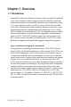
CHAPTER 1 Overview This chapter provides an overview of UNO-3072Lspecifications.
Chapter 1 Overview 1.1 Introduction Standard PCs and some industrial computers with a standard OS and hardware for the consumer market cannot provide the reliability required by industrial automation and embedded industrial control applications. However, many engineers prefer to use PCs because of their advanced functions such as: analog control and simulation, database connectivity, webbased applications, and communication with third-party devices.
An Industry-Proven Design Industrial and mobile applications require controllers with high-vibration specifications and a wide temperature range. Machines or controllers in light industrial environments also require flexible and stable mounting. Many machine builders underestimate the need for a more rugged controller because their end applications are mounted in an industrial enclosure. Advantech UNO-3072Lhas a special design without the weaknesses of a standard PC.
UNO-3072L features onboard DI and DO. These DIs and DOs can be used as 32-bit counters or to handle alarms and events. Any events can be passed to UNO-3072L through DIs with an additional DI plug-in card. UNO-3072L can also output alarms through onboard DOs immediately to notify key personnel about urgent events. Flexible Networking Options UNO-3072Loffers two ways to connect to a network: Ethernet and Modem. The two built-in Ethernet ports provide high-speed networking capability up to 100 Mbps.
1.2 Hardware Specifications • CPU: Celeron M 1GHz CPU (non-cache) Celeron M 1.5GHz CPU ( 1MB cache) • Memory: 1x 200 pin SODIMM socket, supports up to 1GB DDR RAM • BIOS: Award 4MB flash memory, supports Boot-on-LAN function • Interface I/O: VGA/Keyboard/Mouse DB-15 VGA Connector, PS/2 keyboard and mouse • Clock: Battery-backup RTC for time and date • Serial Ports: 2 x RS-232 and 2 x RS-232/422/485 w/ DB-9 connector and Automatic RS-485 data flow control • RS-232 Speed: 50 bps ~ 115.
24 VDC: 4.4 mA (typical) 48 VDC: 9.0 mA (typical) 50 VDC: 9.
1.3 Safety Precautions The following messages inform how to make each connection. In most cases, you will simply need to connect a standard cable. Note: Always disconnect the power cord from your chassis whenever you are working on it. Do not connect while the power is on. A sudden rush of power can damage sensitive electronic components. Only experienced electronics personnel should open the chassis. Note: Always ground yourself to remove any static electric charge before touching UNO-3072L.
1.4 Chassis Dimensions Figure 1.
Figure 1.2: Chassis Dimensions for C-M 1.
1.5 Packing List The accessory package of UNO-3072Lcontains the following items: (A) Power cable (B) Keyboard/ Mouse PS/2 cable (C) Warranty card (D) Driver and Utility CD-ROM (E) 2 x nti-vibration rubber (F) PCI expansion to hold 2nd anti-vibration rubber (G) Mini Jumper (H) Paper menu ( I ) Power connector (J) IDE cable for 2.5" HDD Figure 1.
CHAPTER 2 Hardware Functionality This chapter shows how to setup the UNO-3072Lhardware functions, including connecting peripherals, and setting switches and indicators.
Chapter 2 Hardware Functionality 2.1 Introduction The figures below show the connectors on UNO-3072L, and following sections give you detailed information about function of each peripheral. Figure 2.
2.2 RS-232 Interface (COM1~COM2) The UNO-3072Loffers two industrial standard RS-232 serial communication interface ports: COM1 and COM2. Please refer to Appendix A.4 for their pin assignments. The IRQ and I/O address range of COM1 and COM2 are listed below: COM1: 3F8H, IRQ4 COM2: 2F8H, IRQ3 2.3 RS-232/422/485 Interface (COM3~COM4) The UNO-3072Loffers two industrial RS-232/422/485 serial communication interface ports: COM3 and COM4. Please refer to Appendix A.5 for their pin assignments.
2.3.4 RS-232/422/485 Selection COM3 and COM4 support 9-wire RS-232, RS-422 and RS-485 interfaces. The system detects RS-422 or RS-485 signals automatically in RS-422/ 485 mode. To select between RS-422/485 and RS-232 for COM3, adjust JP4. To select between RS-422/485 and RS-232 for COM4, adjust JP5. You can refer to figures below to set the JP4 and JP5. Note: Please refer to Appendix A.2 Figure A.4 and A.5 for location of JP4 and JP5 location Jumper setting for RS-422/485 interface: (Default setting).
Table 2.1: Auto Flow Control and RS-422 Slave/Master Selection SW2 DIP Switch Setting COM Port Mode Selections COM3 RS-422: Slave mode RS-485: Auto flow control COM4 RS-422: Slave mode RS-485: Auto flow control COM3 RS-422: Master mode RS-485: N/A COM4 RS-422: Slave mode RS-485: Auto flow control COM3 RS-422: Slave mode RS-485: Auto flow control COM4 RS-422: Master mode RS-485: N/A COM3 RS-422: Master mode RS-485: N/A COM4 RS-422: Master mode RS-485: N/A 2.3.
Table 2.2: IRQ Setting via switch 1 at SW3 Switch 1 at SW3 setting 1 2 1 2 Function O N Share IRQ (default) O N Independent IRQ Note: Please Refer to Figure A.4 and A.5 for location of SW3 Note: After changing the jumper, please also adjust the IRQ through the device manager software for the new settings to work properly. (Refer to UNO Serial Port Installation Guide in the CD, steps 7 ~ 10) Table 2.
2.3.7 Termination Resistor (JP6) The onboard termination resistor (120 ohm) for COM3/COM4 can be used for long distance transmission or device matching (Default Open). COM3 COM4 RS-422 TX3-TR RX3-TR TX4-TR TX4-TR Close A Close B Close C Close D RS-485 Data+, DataData+, Data- Close: Enable termination resistor. Note: Please refer to Figure A.4 and A.5 for location of JP6 2.
Figure 2.4: Digital Input Connector Pin Assignments Table 2.4: Digital Input Connector Signal Description Signal Name Reference DI <0...3> COM COM - Direction Description Input Isolated DI signals - DI, DO isolated ground 2.5.2 Isolated Inputs Each of isolated digital input channels accepts 0 ~ 50 VDC voltage inputs, and accepts bi-directional input. The voltage range is -3 ~ 3 VDC for logic 0 (low), -50 ~ -10 VDC and 10 ~ 50 VDC for logic 1 (high).
Figure 2.5: Isolated Digital Input Connection 2.5.3 Interrupt Function of the DI Signals DI0 and DI1 can be used to generate hardware interrupts. A user can setup the configuration of interrupts by programming the interrupt control register. The channels are connected to the interrupt circuitry. Users can disable/ enable interrupt function, select trigger type or latch the port data by setting the Interrupt Control Register of the UNO-3072L(refer to section 2.5.5 below).
2.5.5 Interrupt Control Register Table 2.5: Interrupt Control Register Bit Map Base Address 7 6 5 4 3 2 1 0 202H R/W Interrupt Enable Control/Status Register 203H R/W Interrupt Triggering Edge Control/Status Register DI1EN DI0EN 207H R/W DI1TE DI0TE DI1F DI0F Interrupt Flag/Clear Register The Interrupt Control Register controls the function and status of each interrupt signal source. Table 2.5 shows the bit map of the Interrupt Control Register.
2.5.7 Interrupt Triggering Edge Control The interrupt can be triggered by a rising edge or a falling edge of the interrupt signal, as determined by the value in the interrupt triggering edge control bit in the interrupt control register, as shown in Table 2.7. Table 2.7: Interrupt Triggering Edge Control Bit Values DI0TE & DI1TE Triggering edge of interrupt signal 0 Falling edge trigger 1 Rising edge trigger 2.5.
2.6 Onboard Isolated Digital Output The UNO-3072Lhas 4 isolated DO channels designated DO0 ~ DO3. 2.6.1 Pin Assignments The connector type of UNO-3072Lis plug-in screw terminal block that enables you to connect to field I/O devices directly without additional accessories. Figure 2.7 and Table 2.9 show its pin assignment as well as signal description. Figure 2.6: Digital Output Connector Pin Assignments Table 2.9: Digital Output Connector Signal Description Signal Name Reference DO <0...
Table 2.10: Digital Output Power On Configuration JP7 Power on configuration after hot reset Reset all digital output (default configuration) Keep last status after hot reset 2.6.3 Isolated Outputs Each of isolated output channels comes equipped with a Darlington transistor. All output channels share common emitters.
Figure 2.7: Isolated Digital Output Connection Note: Please refer to Appendix A.3 Table A.6 for command of DO Note: UNO-3072Lprovides built-in examples to show how to deliver digital output functionality. Refer to console mode examples in C:\Program Files\Advantech\UNO\UNO_IsaDIO\Examples\Console. (Please install DI/O driver from the UNO CD to use these examples) 2.
Table 2.
2.7.2 Counter 0 Function Block Figure 2.8: Counter 0 Function Block 2.7.3 Counter 1 Function Block Figure 2.
2.7.4 32-bit Counter Function Block (CTR32Set=1) Figure 2.10: 32-bit Counter Function Block 2.7.5 Counter Clock Source There are two clock sources available for the user counters by setting counter clock control bits - CTR0CLKSet and CTR1CLKSet. Table 2.12: Counter Clock Source Control Bit CTR0CLKSet CTR1CLKSet 0 Internal clock (default) 1 External clock from digital input 1 (DI1) channel 0 Internal clock (default) 1 External clock from digital input 3 (DI3) channel 2.7.
2.7.7 Counter Gate Source The gate sources you select determine what kind of gate input signal to enable your counter/timer when receiving clock input. There are two gate sources available for the user counters by setting gate source control bits CTR0GateSet and CTR1GateSet. Table 2.
Table 2.16: Counter Interrupt Flag Control Bit CTR0F, CTR1F Read Write Counter Interrupt Status 0 No interrupt 1 Interrupt occur 0 Don’t care 1 Clear interrupt CTR0IntSet, CTR1IntSet Counter Interrupt Control 0 Disable (Default) 1 Enable 2.7.10 Cascaded 32-bit Counter You can also cascade counter 0 and counter 1 together as one 32-bit counter/timer, and it’s configured by control bit - CTR32Set. Table 2.
Figure 2.11: Location of Power P1 and P2 You can see the LED indicators to monitor power input situation. (Please refer to Figure 2.13 for location of LED). If the voltage of power input P1> 15 VDC, the P1 LED indicator will be enable (means the first power input is used). It is the same for P2 LED indicator (to show if the voltage of power input P2 > 15 VDC). When any voltage of P1 and P2 < 15VDC, the Fault LED will be enable. It means that you don’t use redundancy power input.
Figure 2.12: LED Indicators Location to Monitor Power Input Situation Table 2.18: Power Register Bit Map 218H R Power Register PWR P2 PWR P1 =0, Power fail =1, Power normal P1 (24V) =0, Power input 1 fail =1, Power input 1 normal P2 (24V*) =0, Power input 2 fail =1, Power input 2 normal 2.9 LED and Buzzer for System Diagnosis In a “headless application” (an application without a monitor display), it is always difficult to know the system status.
Figure 2.13: LED Indicator Location for System Diagnosis Table 2.19: LED and Buzzer Control Register Bit Map 210H R/W DIAG LED Register LEDS1 LEDS0 LEDEn 211H R/W Buzzer Register SPKS1 LEDEn: SPKS0 SPKEn =0, DIAG LED disable =1, DIAG LED enable LEDS0 and LEDS1: LED flickering speed setting bit (refer to Table 2.20) SPKEn: =0, Speaker disable =1, Speaker enable SPKS0 & SPKS1: Buzzer alarming setting bit (refer to Table 2.
Table 2.20: Programmable LED Control Bit LEDS1 LEDS0 Light on 0 0 Fast flicker 0 1 Normal flicker 1 0 Short flicker 1 1 Table 2.21: Programmable Buzzer Control Bit Beep on SPKS1 SPKS0 0 0 Short beep 0 1 Normal beep 1 0 Long beep 1 1 2.10 PS/2 Keyboard and Mouse Connector The UNO-3072Lprovides a PS/2 keyboard and PS/2 mouse connector. A 6-pin mini-DIN connector is located on the front panel. UNO-3072L comes with an adapter in the accessory package (see section 1.
2.12 VGA Display Connector The UNO-3072L provides a VGA controller (Intel 855GME GMCH ICH4 Chipset 400MHz FSB) for a high resolution VGA interface. It supports up to 1280 x 1024 @ 16bpp (60Hz). 2.13 Reset Button Press the "Reset" button to activate the reset function. Note: Please refer to Figure 2.
CHAPTER 3 Initial Setup This chapter introduces how to initialize the UNO-3072L.
Chapter 3 Initial Setup 3.1 Inserting a CompactFlash Card UNO-3072L has one internal CompactFlash slot (CN3). It's used to install O.S and Application Program JP2 on mainboard (refer to Figures A.4 and A.5) Closed: CN3 CompactFlash on mainboard is the master Open: CN3 CompactFlash on mainboard is slave NOTE: 1. Only one CompactFlash can be set as master 2. Internal & external CompactFlash doesn't support Hot Swap 3.
3.3 Installing a Hard Disk The procedure for installing a hard disk into the UNO-3072L is listed below. Please follow these steps carefully. 1. Remove the power cord. 2. Unscrew the two screws from the upper HDD cover 3. Unscrew the four screws from the upper cover and remove it. 4. Install the HDD in HDD bracket and secure with the four screws. 5.
Figure 3.2: 1st Anti-Vibration Rubber 6. Install PCI extension to hold 2nd anti-vibration rubber (Figure 3.3) and screw the 2nd anti-vibration rubber towards the 2nd PCI card until it is fixed. Figure 3.3: 2nd PCI-bus Card Installation 7. Cut off a part of the anti-vibration rubber if it is too long to fit into the box when the PCI card is fixed.
Figure 3.4: Adjust the Size of the Anti-Vibration Rubber 8. Screw back the upper cover with the four screws. 3.5 Mounting UNO-3072L There are 3 types of mounting kits for UNO-3000 series: • Panel mount • Stand mount • Wallmount Pls refer to UNO-3000 Series Accessories Manual Note: Due to thermal performance issues, Wallmount will only support specific models.
3.6 Installing Power Cable UNO-3072Lprovides an internal backup power source so that it can provide power for a CD-ROM, DVD-ROM or other external devices. You can use the power cable from accessory package (see section 1.5). Yellow +12V Black GND Black GND Red +5V Figure 3.
3.7 UNO-3072LMounting Caution Figure 3.6: UNO-3072L Improper Installation (1) Figure 3.
Figure 3.8: UNO-3072LCorrect Installation Note: Because the heat transfer mechanism is designed close to the right side of system, make sure not to attach the right side of the UNO chassis to the wall or ground.(shown in Figure 3.10 and 3.11) It may make the system easy to hang due to the heat transfer issue. Instead, try to allow some space on the right side of UNO chassis. This will make the system easier to transfer heat from the inside to the outside.( refer to Figure 3.12). 3.
APPENDIX A System Settings and Pin Assignments
Appendix A System Settings and Pin Assignments A.1 System I/O Address and Interrupt Assignments Table A.
Table A.2: UNO-3072LInterrupt Assignments Interrupt No.
A.2 Board Connectors and Jumpers There are several connectors and jumpers on the UNO-3072Lboard. The following sections tell you how to configure the UNO-3072Lhardware setting. Figures A.1 to A.7 show the location of UNO-3072Lconnectors and jumpers. Figure A.1: Backplane Connector and Jumper Locations Figure A.
Figure A.3: Mainboard Connector and Jumper Locations (Frontside) Table A.
Table A.
A.3 UNO-3072LControl Register Table A.
A.4 RS-232 Standard Serial Port (COM1~COM2) Table A.
A.5 RS-232/422/485 Serial Port (COM3~COM4) Table A.7: RS-232/422/485 Serial Port Pin Assignments Pin RS-232 RS-422 RS-485 1 DCD Tx- DATA- 2 RxD Tx+ DATA+ 3 TxD Rx+ NC 4 DTR Rx- NC 5 GND GND GND 6 DSR NC NC 7 RTS NC NC 8 CTS NC NC 9 RI NC NC A.6 Ethernet RJ-45 Connector (LAN1~LAN2) Table A.
A.7 Power Screw Terminal (PWR) Figure A.8: Power Connector Pin Assignments Table A.
A.8 PS/2 Keyboard and Mouse Connector Table A.10: Keyboard and Mouse Connector Pin Assignments Pin Signal Name 1 KB DATA 2 MS DATA 3 GND 4 VCC 5 KB Clock 6 MS Clock A.9 USB Connector (USB1~USB4) Table A.
A.10 VGA Display Connector Table A.
APPENDIX B Programming the Watchdog Timer
Appendix B Programming the Watchdog Timer Below are samples of code for controlling the Watchdog Timer function.