
User manual

UNO-3072L User Manual 24
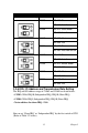
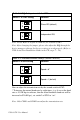
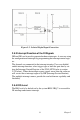
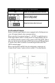
Figure 2.7:
Isolated Digital
Output Connection
Note: Please refer to Appendix A.3 Table A.6 for command of DO
Note:
UNO-3072Lprovides built-in examples to show how to deliver
digital output functionality. Refer to console mode examples in C:\Pro-
gram Files\Advantech\UNO\UNO_IsaDIO\Examples\Console. (Please
install DI/O driver from the UNO CD to use these examples)
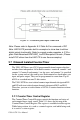
2.7 Onboard Isolated Counter/Timer
The UNO-3072Luses one 82C54 programmable timer/counter
chip that
includes
three independent 16-bit
down
counters: counter 0,
counter 1 and
counter 2.
Counter 0 and counter
1 are
for users, and counter 2 is specified
for
the
system and can’t be
used by user.
Each counter has
clock input,
gate
input and pulse output. They can be programmed to count from 2 up to
65535
or cascaded into one 32-bit
counter.
The UNO-3072Lhas two isolated counter input channels designated DI1
and DI3 with two isolated output channels designated DO2 and DO3.
Therefore,
you
can set
each counter of 82C54
as
counter function or timer
function.
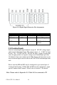
2.7.1
Counter/Timer Control
Register
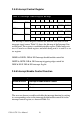
The Counter/Timer Control Register controls the
function and
status
of
each counter/timer signal
source. Table
2.11
shows
the bit map of the
Counter/Timer Control Register. The register is readable/writable register.
While being written, it
is used
as a control register;
and
while
being read,
it
is used as
a status
register.