
User manual

23 Chapter 2
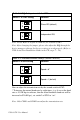
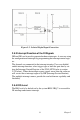
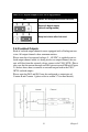
2.6.3
Isolated
Outputs
Each of isolated
output channels
comes equipped with a
Darlington tran-
sistor. All output
channels share common emitters.
Please note
that if
an external
voltage (5
~ 40
VDC) is applied to
an iso-
lated output
channel while it is being used as an output
channel, the cur-
rent will flow from
the external voltage source
to the UNO-3072L. Please
take care that the
current through each
DO pin
not exceed 200
mA. Figure
2.8 below shows how
to connect
an
external
output load
to the UNO-
3072L isolated outputs.
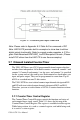
Please
note that
DO2 and DO3
may be configured
as
output pins of
Counter 0 and Counter
1 (please refer to section
2.7 for
more details)
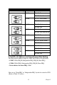
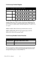
Table 2.10: Digital Output Power On Configuration
JP7
Power on configuration after hot reset
Reset all digital output
(default configuration)
Keep last status after hot reset