
User manual

UNO-3072L User Manual 22
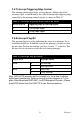
2.6 Onboard Isolated Digital Output
The UNO-3072Lhas 4 isolated DO channels designated DO0 ~ DO3.
2.6.1
Pin
Assignments
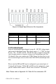
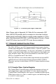
The connector type of UNO-3072Lis
plug-in screw terminal block
that
enables
you to connect to field I/O
devices directly without additional
accessories. Figure 2.7 and Table 2.9 show its pin assignment as well as
signal description.
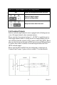
Figure 2.6:
Digital Output Connector
Pin Assignments
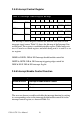
2.6.2
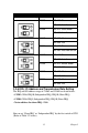
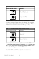
Power On Configuration
Default configuration
after power on or
hardware reset is to set all the iso-
lated digital
output channels
to open status
(the current
of the load
can’t be
sink) so
that users need
not
worry
about damaging
external devices during
system
startup or reset. When
the
system is hot reset, then
the status
of iso-
lated digital
output channels are selected by
jumper JP7. Table 2.10
shows
the configuration of
jumper JP7.
Note: Please refer to Figure A.4 and A.5 for location of JP7
Table 2.9: Digital Output Connector Signal Description
Signal Name Reference Direction Description
DO <0...3> COM Output Isolated DO signals
COM - - DI, DO isolated
ground