
User manual

19 Chapter 2
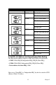
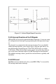
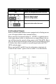
Figure 2.5:
Isolated Digital
Input Connection
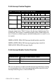
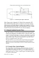
2.5.3
Interrupt Function of the DI Signals
DI0 and
DI1 can be used to generate hardware
interrupts. A user can setup
the configuration of interrupts
by
programming the interrupt control regis-
ter.
The channels are connected to the interrupt circuitry.
Users can
disable/
enable interrupt
function, select trigger
type or
latch the port data
by
set-
ting
the Interrupt Control Register of the
UNO-3072L(refer to section
2.5.5 below). When
the interrupt request
signals occur,
then the software
will service
these
interrupt requests by
ISR (Interrupt Service
Routine).
The
multiple
interrupt sources provide
the
card with more
capability and
flexibility.
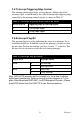
2.5.4
IRQ Level
The IRQ level is by default set by the system BIOS. IRQ 7 is reserved for
DI
interrupt and counter
interrupt.