
User manual


Table Of Contents
- Chapter 1 UNO-1140/F/FH Overview
- Chapter 2 Hardware Functionality
- 2.1 UNO-1140/F/FH Peripherals
- 2.2 COM1~COM4: RS-232/485 Interfaces
- 2.3 COM5~COM8: RS-485 Interfaces (UNO-1140F/FH)
- 2.4 LAN: Ethernet Connector
- 2.5 Power Connector
- 2.6 LED Indicators
- 2.7 PS/2 Keyboard and Mouse Connector
- 2.8 Universal Serial Bus Connectors
- 2.9 VGA: VGA Display Connector
- 2.10 RESET: Reset Button
- Chapter 3 Initial Setup
- Appendix A Pin Assignments
- Appendix B USB Holder Installation
UNO-1140/F/FH User Manual 24
A.8 VGA Display Connector
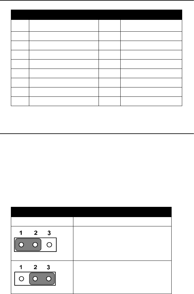
A.9 Clear CMOS (CMOS1)
This jumper is used to erase CMOS data and reset system BIOS informa-
tion. Follow the procedures below to clear the CMOS.
1. Turn off the system.
2. Close jumper CMOS1 (2-3) to clear CMOS.
3. Remove jumper CMOS1 (2-3)
4. Turn on the system. The CMOS is now cleared and BIOS is reset to
its default setting.
Table A.8: VGA Adaptor Cable Pin Assignments
Pin Signal Name Pin Signal Name
1 RED 9 EDID Power
2 GREEN 10 GND
3BLUE 11 NC
4NC 12 NC
5 GND 13 H-SYNC
6 GND 14 V-SYNC
7GND 15 NC
8GND
Table A.9: CMOS1 setting for Clear CMOS
Configuration Function
Normal ( Default)
Clear CMOS