
User manual


Table Of Contents
- Chapter 1 UNO-1140/F/FH Overview
- Chapter 2 Hardware Functionality
- 2.1 UNO-1140/F/FH Peripherals
- 2.2 COM1~COM4: RS-232/485 Interfaces
- 2.3 COM5~COM8: RS-485 Interfaces (UNO-1140F/FH)
- 2.4 LAN: Ethernet Connector
- 2.5 Power Connector
- 2.6 LED Indicators
- 2.7 PS/2 Keyboard and Mouse Connector
- 2.8 Universal Serial Bus Connectors
- 2.9 VGA: VGA Display Connector
- 2.10 RESET: Reset Button
- Chapter 3 Initial Setup
- Appendix A Pin Assignments
- Appendix B USB Holder Installation
UNO-1140/F/FH User Manual 20
Appendix A Pin Assignments
A.1 Board Connectors and Jumpers
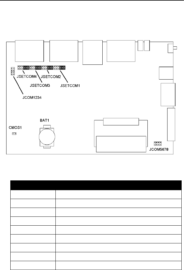
There are connectors and jumpers on the UNO-1140/F/FH board. The
following sections tell you how to configure the UNO-1140/F/FH hard-
ware setting. Figure A-1 and figure A-2 show the locations of UNO-
1140/F/FH connectors and jumpers.
Figure A.1: Connector & Jumper Locations (Top)
Table A.1: Jumper Location
Location Function
CMOS1 Clear CMOS
BAT1 Battery for RTC
JSETCOM1 RS-232/485 Selection for COM1
JSETCOM2 RS-232/485 Selection for COM2
JSETCOM3 RS-232/485 Selection for COM3
JSETCOM4 RS-232/485 Selection for COM4
JCOM1234 Terminal Resistor Setting for COM1~COM4
JCOM5678 Terminal Resistor Setting for COM5~COM8