
User manual


Table Of Contents
- Chapter 1 UNO-1140/F/FH Overview
- Chapter 2 Hardware Functionality
- 2.1 UNO-1140/F/FH Peripherals
- 2.2 COM1~COM4: RS-232/485 Interfaces
- 2.3 COM5~COM8: RS-485 Interfaces (UNO-1140F/FH)
- 2.4 LAN: Ethernet Connector
- 2.5 Power Connector
- 2.6 LED Indicators
- 2.7 PS/2 Keyboard and Mouse Connector
- 2.8 Universal Serial Bus Connectors
- 2.9 VGA: VGA Display Connector
- 2.10 RESET: Reset Button
- Chapter 3 Initial Setup
- Appendix A Pin Assignments
- Appendix B USB Holder Installation
UNO-1140/F/FH User Manual 18
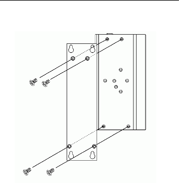
3.6 Wallmounting Setup
Please follow the below steps to mount the UNO-1140/F/FH on the wall.
1. Screw the provided Wall Mounting Kit on the rear side of UNO-
1140/F/FH as the diagram shown below.
2. Mount the device on the wall by the 2 pairs hooking hole provided
by the Wallmounting Kit.
Note: To get the UNO-1140/F/FH down from the rail, push the
device top to down then pull the bottom of the device to
let it off the rail smoothly.