
User manual


Table Of Contents
- Chapter 1 UNO-1140/F/FH Overview
- Chapter 2 Hardware Functionality
- 2.1 UNO-1140/F/FH Peripherals
- 2.2 COM1~COM4: RS-232/485 Interfaces
- 2.3 COM5~COM8: RS-485 Interfaces (UNO-1140F/FH)
- 2.4 LAN: Ethernet Connector
- 2.5 Power Connector
- 2.6 LED Indicators
- 2.7 PS/2 Keyboard and Mouse Connector
- 2.8 Universal Serial Bus Connectors
- 2.9 VGA: VGA Display Connector
- 2.10 RESET: Reset Button
- Chapter 3 Initial Setup
- Appendix A Pin Assignments
- Appendix B USB Holder Installation
UNO-1140/F/FH User Manual 16
Chapter 3 Initial Setup
3.1 CompactFlash Installation
The procedure for installing a CompactFlash card into the UNO-1140/F/
FH is as follows, please follows these steps carefully.
1. Remove the power.
2. Unscrew six screws of the rear cover of UNO-1140/F/FH.
3. Remove the rear cover.
4. Plug a CompactFlash card with user’s OS and application program
into a CompactFlash card slot on board.
5. Screw back the rear cover with the six screws.
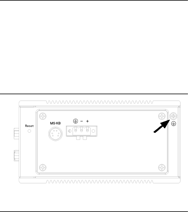
3.2 Chassis Grounding
Figure 3.1: Chassis Grounding Connection
3.3 Power Connection
Connect the UNO-1140/F to a 9 ~ 36 V
DC
power source or the UNO-
1140FH to a 10~30V
DC
power source. The power source can either be
from a power adapter or an in-house power source.