
User manual


Table Of Contents
- Chapter 1 UNO-1140/F/FH Overview
- Chapter 2 Hardware Functionality
- 2.1 UNO-1140/F/FH Peripherals
- 2.2 COM1~COM4: RS-232/485 Interfaces
- 2.3 COM5~COM8: RS-485 Interfaces (UNO-1140F/FH)
- 2.4 LAN: Ethernet Connector
- 2.5 Power Connector
- 2.6 LED Indicators
- 2.7 PS/2 Keyboard and Mouse Connector
- 2.8 Universal Serial Bus Connectors
- 2.9 VGA: VGA Display Connector
- 2.10 RESET: Reset Button
- Chapter 3 Initial Setup
- Appendix A Pin Assignments
- Appendix B USB Holder Installation
UNO-1140/F/FH User Manual 8
Chapter 2 Hardware Functionality
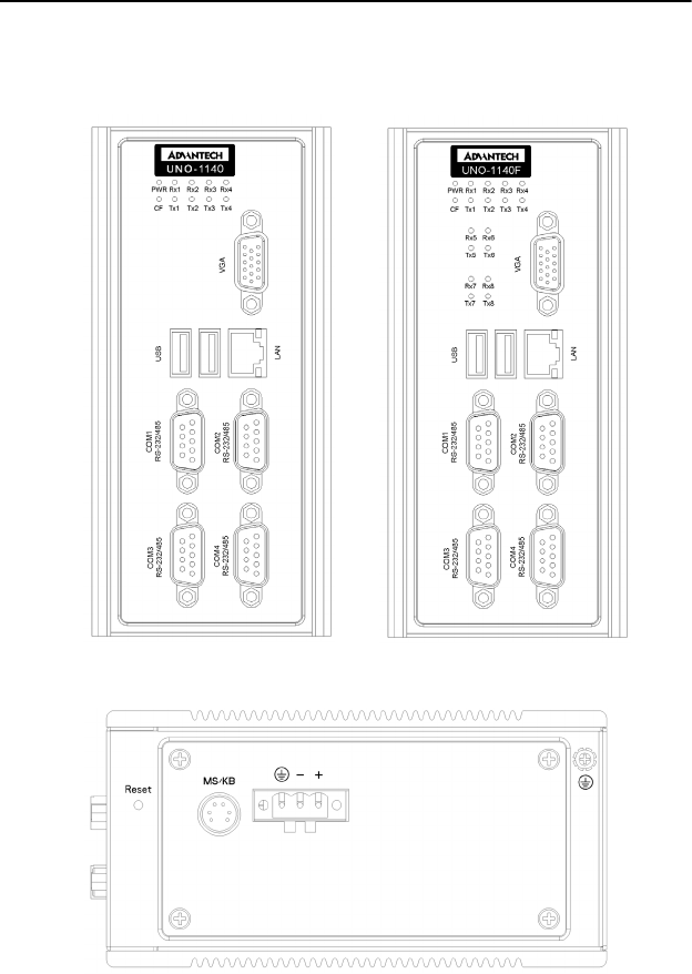
2.1 UNO-1140/F/FH Peripherals
The following figures show the connectors on UNO-1140/F/FH. The fol-
lowing sections give you detailed information about function of each
peripheral.
Figure 2.1: UNO-1140/F/FH Front Views
Figure 2.2: UNO-1140 Top View