UNO-1140/F Advantech EVA x86 SoC Fanless Box PC with 1 x LAN, 8 x Isolated COM User Manual
Copyright Notice The documentation and the software included with this product are copyrighted 2009 by Advantech Co., Ltd. All rights are reserved. Advantech Co., Ltd. reserves the right to make improvements in the products described in this manual at any time without notice. No part of this manual may be reproduced, copied, translated or transmitted in any form or by any means without the prior written permission of Advantech Co., Ltd.
Product Warranty (2 years) Advantech warrants to you, the original purchaser, that each of its products will be free from defects in materials and workmanship for two years from the date of purchase. This warranty does not apply to any products which have been repaired or altered by persons other than repair personnel authorized by Advantech, or which have been subject to misuse, abuse, accident or improper installation.
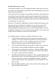
CE This product has passed the CE test for environmental specifications when shielded cables are used for external wiring. FCC Class A This equipment has been tested and found to comply with the limits for a Class A digital device, pursuant to part 15 of the FCC Rules. These limits are designed to provide reasonable protection against harmful interference when the equipment is operated in a commercial environment.
Safety Instructions 1. Read these safety instructions carefully. 2. Keep this User's Manual for later reference. 3. Disconnect this equipment from any AC outlet before cleaning. Use a damp cloth. Do not use liquid or spray detergents for cleaning. 4. For plug-in equipment, the power outlet socket must be located near the equipment and must be easily accessible. 5. Keep this equipment away from humidity. 6. Put this equipment on a reliable surface during installation.
-20° C (-4° F) OR ABOVE 75° C (167° F). THIS COULD DAMAGE THE EQUIPMENT. THE EQUIPMENT SHOULD BE IN A CONTROLLED ENVIRONMENT. 16. CAUTION: DANGER OF EXPLOSION IF BATTERY IS INCORRECTLY REPLACED. REPLACE ONLY WITH THE SAME OR EQUIVALENT TYPE RECOMMENDED BY THE MANUFACTURER, DISCARD USED BATTERIES ACCORDING TO THE MANUFACTURER'S INSTRUCTIONS. The sound pressure level at the operator's position according to IEC 7041:1982 is no more than 70 dB (A).
Contents Chapter 1 UNO-1140/F Overview.................................... 2 1.1 1.2 1.3 1.4 1.5 Chapter 2 Hardware Functionality ................................. 8 2.1 2.2 2.3 2.4 2.5 2.6 2.7 2.8 2.9 2.10 Chapter Introduction ....................................................................... 2 Hardware Specifications ................................................... 2 Safety Precautions ............................................................. 4 UNO-1140/F Series..........................
UNO-1140/F User Manual viii
CHAPTER 1 UNO-1140/F Overview Sections include: • Introduction • Hardware Specifications • Safety Precautions • UNO-1140/F Series • Chassis Dimensions
Chapter 1 UNO-1140/F Overview 1.1 Introduction UNO-1140/F is a DIN-rail mounted Fanless Box PC, which provides several serial communication ports. With a compact size, small foot print and front accessible I/Os, UNO-1140/F is very convenient for wiring and DIN-rail installation in the control cabinet. The wide operation temperature and industrial serial port design makes UNO-1140/F a perfect communication gateway even in critical environments.
Environment • Ingress Protection IP40 • Operating Temperature IEC 68 2-2 (with 100% CPU/ I/O loading) -20 ~ 75° C (-4 ~ 167° F) • Operating Humidity 20 ~ 95% (non-condensing) • Shock Protection IEC 68 2-27CompactFlash: 50 G @ wall mount, half sine, 11 ms • Vibration Protection IEC 68 2-64 (Random 1 Oct./min, 1hr/axis.
1.3 Safety Precautions The following sections tell how to make each connection. In most cases, you will simply need to connect a standard cable. All of the connector pin assignments are shown in Appendix A. Warning!! Always disconnect the power cord from your chassis when you are working on it. Do not connect while the power is on. A sudden rush of power can damage sensitive electronic components. Only experienced electronics personnel should open the chassis.
1.5 Chassis Dimensions 3.00 71.00 152.00 139.00 Figure 1.
UNO-1140/F User Manual 6
CHAPTER 2 Hardware Functionality Sections include: •UNO-1140/F Peripherals •COM1~COM4: RS-232/485 Interfaces •COM5~COM8: RS-485 Interfaces •LAN: Ethernet Connector •Power Connector •LED Indicators •PS/2 Keyboard and Mouse Connector •Universal Serial Bus Connectors •VGA: VGA Display Connector •RESET: Reset Button
Chapter 2 Hardware Functionality 2.1 UNO-1140/F Peripherals The following figures show the connectors on UNO-1140 and UNO1140F. The following sections give you detailed information about function of each peripheral. Figure 2.1: UNO-1140/F Front Views Figure 2.
Figure 2.3: UNO-1140F Top View 2.2 COM1~COM4: RS-232/485 Interfaces The UNO-1140/F offers four RS-232/485 serial communication interface ports, and they are COM1 ~ COM4. Each port can be configured individually to either RS-232 or RS-485 by using on-board jumpers. Please refer to A.2 for pin assignments. The default setting of each port are RS-232. 2.2.
2.2.2 RS-232/485 Selection COM1 ~ COM4 support 9-wire RS-232 and RS-485 interfaces, and you can set corresponding jumpers to select serial ports as RS-232 or RS-485 interfaces shown in Table 2.2. Please note to reset the system to adapt this configuration change. Table 2.1: Selecting RS-232/485 (COM1~COM4) Serial Port Corresponding Jumper to Select RS-232/485 COM1 JSETCOM1 COM2 JSETCOM2 COM3 JSETCOM3 COM4 JSETCOM4 Jumper Setting for RS-232 Interface: (Default Setting) Figure 2.
2.2.3 Terminal Resistor Setup for RS-485 The onboard termination resistor (120 Ohm) for each COM port can be used for long distance transmission or device matching. (Default Open.) Each terminal resistor responds to different channels for RS-422/485. Usually, these resistors are needed for both ends of the communication wires and the value of the resistors should match the characteristic impedance of the wires used. Table 2.
2.4 LAN: Ethernet Connector UNO-1140/F leverage the SOC EVA-4150's internal Ethernet LAN controller that is fully compliant with IEEE 802.3u 10/100Base-T CSMA/CD standards. The Ethernet port provides a standard RJ-45 jack onboard, and LED indicators on the front side to show its Link (Yellow LED) and Active (Green LED) status. Please refer to A.4 for its pin assignments. 2.
The UNO-1140/F provides two connectors with USB interfaces, which gives complete Plug & Play and hot swapping for up to 127 external devices. The USB interface complies with USB specification version 1.1 compliant. OpenHCI, Rev. 1.0. The USB interface can be disabled in the system BIOS setup. Please refer to Appendix A.7 for its pin assignments. 2.9 VGA: VGA Display Connector The UNO-1140/F provides a VGA controller for a high resolution VGA interface.
UNO-1140/F User Manual 14
CHAPTER 3 Initial Setup Sections include: • CompactFlash Installation • Chassis Grounding • Power Connection • BIOS Setup and System Assignments • DIN-rail Mounting Setup • Wallmounting Setup
Chapter 3 Initial Setup 3.1 CompactFlash Installation The procedure for installing a CompactFlash card into the UNO-1140/F is as follows, please follows these steps carefully. 1. Remove the power. 2. Unscrew six screws of the rear cover of UNO-1140/F. 3. Remove the rear cover. 4. Plug a CompactFlash card with user’s OS and application program into a CompactFlash card slot on board. 5. Screw back the rear cover with the six screws. 3.2 Chassis Grounding Figure 3.1: Chassis Grounding Connection 3.
3.4 BIOS Setup and System Assignments Press "DEL" in the boot-up screen to enter the BIOS setup utility. Please follow the instruction on the screen to do the necessary settings. Please note that you can try to “LOAD BIOS DEFAULTS” from the BIOS Setup manual if UNO-1140/F does not work properly. 3.5 DIN-rail Mounting Setup Please follow these steps to mount the UNO-1140/F on a DIN-rail. 1. Screw the provided DIN-rail Kit on the rear side of UNO-1140/F as the diagram shown below. 2.
Note: To get the UNO-1140/F down from the rail, push the device top to down then pull the bottom of the device to let it off the rail smoothly. 3.6 Wallmounting Setup Please follow the below steps to mount the UNO-1140/F on the wall. 1. Screw the provided Wall Mounting Kit on the rear side of UNO1140/F as the diagram shown below. 2. Mount the device on the wall by the 2 pairs hooking hole provided by the Wallmounting Kit.
APPENDIX A Pin Assignments This appendix shows the UNO-1140/F pin assignments •Board Connectors and Jumpers •RS-232/485 Serial Port (COM1~COM4) •RS-485 Serial Port (COM5~COM8) •Ethernet RJ-45 Connector •Power Screw Terminal •PS/2 Keyboard and Mouse Connector •USB Connector •VGA Display Connector •Clear CMOS (CMOS1)
Appendix A Pin Assignments A.1 Board Connectors and Jumpers There are connectors and jumpers on the UNO-1140/F board. The following sections tell you how to configure the UNO-1140/F hardware setting. Figure A-1 and figure A-2 show the locations of UNO-1140/F connectors and jumpers. Figure A.1: Connector & Jumper Locations (Top) Table A.
A.2 RS-232/485 Serial Port (COM1~COM4) Table A.
A.3 RS-485 Serial Port (COM5~COM8, UNO-1140F) The S-GND is for Shielding Ground A.4 Ethernet RJ-45 Connector Table A.3: Ethernet RJ-45 Connector Pin Assigns Pin 10/100Base-T Signal Name 1 2 3 4 5 6 7 8 XMT+ XMTRCV+ NC NC RCVNC NC A.5 Power Screw Terminal (CN8) Table A.
A.6 PS/2 Keyboard and Mouse Connector (CN10) Table A.5: 6 5 3 4 2 1 Table A.6: Keyboard & Mouse Connector Pin Assigns Pin Signal Name 1 KB DATA 2 MS DATA 3 GND 4 VCC 5 KB CLOCK 6 MS CLOCK A.7 USB Connector Table A.
A.8 VGA Display Connector Table A.8: VGA Adaptor Cable Pin Assignments Pin Signal Name Pin Signal Name 1 RED 9 EDID Power 2 GREEN 10 GND 3 BLUE 11 NC 4 NC 12 NC 5 GND 13 H-SYNC 6 GND 14 V-SYNC 7 GND 15 NC 8 GND A.9 Clear CMOS (CMOS1) This jumper is used to erase CMOS data and reset system BIOS information. Follow the procedures below to clear the CMOS. 1. Turn off the system. 2. Close jumper CMOS1 (2-3) to clear CMOS. 3. Remove jumper CMOS1 (2-3) 4.