
User manual

7 UNO-1110 User Manual
Chapter 2 Installation
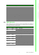
2.2 LED Indicators
LEDs to display the power, SD, Ethernet, Serial, Programmable LED and Digital I/O
status are located on the front panel of UNO-1110, and each of them has its own spe-
cific meaning, as shown in the table below.
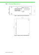
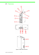
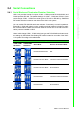
Table 2.1: UNO-1110 I/O Overview
Item Description
1 LED Indicators
2VGA
3 Ethernet Ports
4 Serial Ports
5USB Ports
6 Reset Button
7 Simulation DI
8 Power Inputs
9 Chassis Grounding
10 Digital I/O
11 RS-485
12 SD Slots
13 COM Port Setting DIP Switch
14 Debug Port
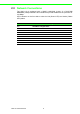
Table 2.2: UNO-1110 LED Indicator Definitions
LED Color Status Description
PWR Red
On System power is on
Off System power is off
SD Green Flash Data is transmitting/receiving
Tx1 ~ Tx4 Yellow Flash Serial port COM1 - COM4 is transmitting data
Rx1 ~ Rx4 Green Flash Serial port COM1 - COM4 is receiving data
PL1 ~ PL4 Green
On User Programmable LED on
Off User Programmable LED off
DI0 ~ DI3
Green/
Yellow
On Input High
Off Input Low
DO0 ~ DO1
Green/
Yellow
On Set False
Off Set True
LAN Link Green
On Connected to network
Off Not connected to network
Flash Data is transmitting / receiving
LAN Speed Yellow
On Link to 100 Mbps network
Off Link to 10 Mbps network