TPC-61S Series ARM9 Touch Panel Computers with 5.
Copyright The documentation and the software included with this product are copyrighted 2005 by Advantech Co., Ltd. All rights are reserved. Advantech Co., Ltd. reserves the right to make improvements in the products described in this manual at any time without notice. No part of this manual may be reproduced, copied, translated or transmitted in any form or by any means without the prior written permission of Advantech Co., Ltd. Information provided in this manual is intended to be accurate and reliable.
Product Warranty (1 year) Advantech warrants to you, the original purchaser, that each of its products will be free from defects in materials and workmanship for one year from the date of purchase. This warranty does not apply to any products which have been repaired or altered by persons other than repair personnel authorized by Advantech, or which have been subject to misuse, abuse, accident or improper installation.
CE This product has passed the CE test for environmental specifications. FCC Class B This equipment has been tested and found to comply with the limits for a Class B digital device, pursuant to Part 15 of the FCC Rules. These limits are designed to provide reasonable protection against harmful interference in a residential installation.
7. Make sure the voltage of the power source is correct before connecting the equipment to the power outlet. 8. Position the power cord so that people cannot step on it. Do not place anything over the power cord. 9. All cautions and warnings on the equipment should be noted. 10. If the equipment is not used for a long time, disconnect it from the power source to avoid damage by transient overvoltage. 11. Never pour any liquid into an opening. This may cause fire or electrical shock. 12.
mended by the manufacture. Discard used batteries according to the manufacturer’s instructions. Wichtige Sicherheishinweise 1. Bitte lesen sie Sich diese Hinweise sorgfältig durch. 2. Heben Sie diese Anleitung für den späteren Gebrauch auf. 3. Vor jedem Reinigen ist das Gerät vom Stromnetz zu trennen. Verwenden Sie Keine Flüssig-oder Aerosolreiniger. Am besten dient ein angefeuchtetes Tuch zur Reinigung. 4. Die NetzanschluBsteckdose soll nahe dem Gerät angebracht und leicht zugänglich sein. 5.
c - Das Gerät war Feuchtigkeit ausgesetzt. d - Wenn das Gerät nicht der Bedienungsanleitung entsprechend funktioniert oder Sie mit Hilfe dieser Anleitung keine Verbesse Technical Support and Assistance Step 1. Visit the Advantech web site at www.advantech.com/support where you can find the latest information about the product. Step 2. Contact your distributor, sales representative, or Advantech's customer service center for technical support if you need additional assistance.
TPC-60S Series User Manual viii
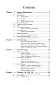
Contents Chapter Chapter 1 General Information ....................................... 2 1.1 1.2 Introduction ....................................................................... 2 Specifications .................................................................... 2 1.3 1.4 1.5 1.6 LCD Specifications ........................................................... 4 Touchscreen Specifications............................................... 4 Power...........................................................
4.1.2 4.1.3 4.1.4 4.2 Networking...................................................................... 34 4.2.1 4.2.2 4.2.3 4.3 Figure 4.2:Soft-Keyboard ............................................ 21 TPC Configuration ....................................................... 21 Figure 4.3:TPC Configurator ....................................... 22 Figure 4.4:General ....................................................... 22 Figure 4.5:Network ......................................................
Figure 4.37:Starting a New Project .............................. 47 Figure 4.38:Selecting ................................................... 47 Figure 4.39:Compiling Your Program ......................... 48 4.4 Wireless LAN Utility for TPC-61S................................. 49 Figure 4.40:Open WLAN Utility ................................ 49 Figure 4.41:Select a Network ...................................... 50 Figure 4.42:Wireless Properties ................................... 50 Figure 4.
TPC-60S Series User Manual xii
CHAPTER 1 2 General Information This chapter gives background information for the TPC-60S series.
Chapter 1 General Information 1.1 Introduction The TPC-60 series of touch panel computers consist of state-of-the-art HMI (Human Machine Interfaces). The 5.7” operator interface combined with a RISC-based computing platform offers these key features: • Bright Display: The high-brightness CSTN LCD display provides a clear interface. • Fanless: By using a low power processor, the system does not have to rely on fans, which often are unreliable, and attracts dust.
1.2.2 I/O Ports • 3 serial ports: two RS-232 (COM1, COM2); one RS-485 (COM4) or one RS-232(COM3) Note TPS-60S provides three serial ports. The third one can be set as COM3 for RS-232 or COM4 for RS-485. Note: It is suggested to use hardware flow control in order to avoid data loss. • 1 RJ-45 Ethernet port • 2 USB ports compliant with USB 1.1: one USB Host (Type A) and one USB Client (Type B) • 1 CompactFlash 2.0 type I/II slot 1.2.3 Storage TPC-60S panel computers provide two methods for storage.
1.3 LCD Specifications Display Type Color STN LCD Size (diagonal) 5.7” Maximum Resolution 320 x 240 (QVGA) Maximum Colors 256 Pixel Pitch (W x H, mm) 0.12 x 0.36 Viewing Angle 110° Luminance (cd / m2) 201 Contrast Ratio 10 Operating Temperature (¢J) 0 ~ 50 (Ambient) Control Contrast Adjustable Backlight 1 CCFL Backlight MTBF 40,000 hours 1.
1.5 Power • Input Voltage: 24 VDC (the fuse will become an open circuit if input level exceeds 33 VDC) • Maximum Current: 2 A 1.6 I/O Ports Arrangement TPC-60S panel computers provide 3 serial ports, 1 Ethernet LAN port and 2 USB ports. The arrangement of the I/O ports is shown in Figure 1.1. Figure 1.
1.7 Panel Mounting There is an adhesive waterproof gasket on the Al-Mg front bezel. Make sure the waterproof gasket is in position before installing a TPC-60 panel computer into the panel opening. 1. Install the panel computer into the panel opening. 2. Find the eight clampers and eight long screws in the accessory pack. Hook these clampers to the holes around the four sides of the bezel. Insert the screws into every clamper and fasten them.
1.8 Exploded Diagram Figure 1.
1.9 Dimensions and Cutout • Weight: 0.8 Kg • Dimensions (WxHxD): 195 x 148 x 44.5 mm • Cutout: 188 x 141 mm (suggested) Figure 1.
CHAPTER 2 2 System Setup This chapter provides a brief explanation for operating the TPC-60S.
Chapter 2 System Setup You can quickly get up and running by following the step-by-step instructions below. 1. Open the package. Please check the packing list at the beginning of this manual to make sure every item is there. Figure 2.1: Unpack the Package 2. Connect the power connector to the 24 VDC power lines. The power lines can either be from some power adapter or an in-house power source. Figure 2.
Figure 2.3: Pin Assignment on the Power Receptor Warning 3. The system may be damaged when the power is turned on if the power source is not connected to the correct pins. Plug the power lines into the system power receptor. Figure 2.
4. Turn on the System Figure 2.5: Turn on the System 5. Calibrate the touchscreen. The detailed procedure is described in section 3.2.
CHAPTER 3 2 System Tuning Sections include: • LCD Contrast Tuning • Touchscreen Calibration • Buzzer Setting
Chapter 3 System Tuning 3.1 LCD Contrast Tuning The display settings let you control the backlight. Backlight provides a screen saving function. The backlight can be automatically turned off when the device is no longer used to lengthen the device life. Please go to “Start” ! “Setting” ! “Control Panel” ! “Display” as shown in the Figure below. Figure 3.
Click the “Advanced” button to activate the advanced backlight utility as shown in Figure 3.3. Click the “+” button to increase the LCD brightness or contrast, or the “-” button to decrease the LCD brightness or contrast. You can also click the slider, hold it, and move it to the designed value and then release the button. Figure 3.3: Advanced Backlight Utility 3.
The window of the stylus properties will display after you click the stylus. There are two tabs in this screen: Double-Tap and Calibration. DoubleTap is used to record the time period between the two taps when doubletapping in Windows CE. Calibration is for users to calibrate the touch screen. Figure 3.5: Stylus Properties Please press “Calibration” and then click “Recalibrate” to calibrate the touch screen as shown below.
3.3 Buzzer Setting TPC-60S panel computers provide a buzzer setting in Windows CE .NET 4.2. This function enables a beep when users use the touch screen. To enable/disable this functionality, open “Start” ! “Setting” ! “Control Panel” ! “Volume & Sounds” as shown in Figure 3.7. Figure 3.7: Volume & Sounds Settting 1 As shown in Figure 3.8, you can enable/disable this functionality or set the frequency. Figure 3.
Users can change the frequency of sounds by opening "Start"->"Setting">"Control Panel"-> "Buzzer Setting" as shown in the figure 3.9. Figure 3.9: Buzzer Setting 1 Set the frequency of sounds as shown in Figure 3.10. Figure 3.
CHAPTER 4 2 Windows CE .NET 4.
Chapter 4 Windows CE .NET 4.2 The TPC-60S operator interface terminals are designed for Windows CE. Windows CE is a compact operating system that occupies less storage space and use less system resources compared with other operating systems. By its modular nature, it is possible to choose the functions that are useful for a specific application. This not only reduced the system resources required, it also reduces start-up time.
4.1 TPC Utilities There are several utilities built into Windows CE .NET in the TPC series. 4.1.1 Soft-Keyboard The TPC-60 series also has a small-sized operator interface. Since it is not convenient to attach a keyboard to such a small device, a software keyboard is built into the standard Windows CE .NET OS. Upon boot-up, a small keyboard icon will appear on the status bar. Tap this icon with the stylus to activate/hide this Soft-keyboard. Figure 4.2: Soft-Keyboard 4.1.
Figure 4.3: TPC Configurator General Page This page displays the basic system information. There are two main parts: system and memory. The system shows the OS image version and CPU type. The second part includes total capacity, usage and currently available capacity of the disk and the memory. Figure 4.
Network This page shows information about the active network adapter. You can select the network adapter from the combo box as shown in Figure 4.5. Release the current IP and retrieve the new IP through the provided button, “Renew”. Use the “Ping” button to ping a specified IP address if you wish to test the connection. Figure 4.5: Network You can get more detailed IP information through “Advanced Network”.
WatchDog Watchdog is a function to let the device automatically reset if a program does not respond in time. This prevents system crashes and hangs to stop your critical applications, as the watchdog will automatically restart the machine when required. Set the response time through the combo box as shown below. The timer is the period that the watchdog will wait for a response. Figure 4.7: WatchDog Setting Only when you select a time span and enable the watchdog, will the response time be effective.
Misc There are several functions provided in the Misc page as shown in the figure below. Figure 4.8: Misc Page CompactFlash Disk Folder Name: There is a pull-down menu to set the folder name of the CompactFlash memory card. The default folder name is “Storage Card”. Warning Do NOT try to key in the folder name in the text box directly. If the CompactFlash folder is renamed to some name that is beyond the given list, there will be irreversible problems for users’ application program settings.
Reboot: You can reboot TPC-60S panel computers by clicking the “Reboot” button. Once this button is clicked, the dialog below will be displayed. Figure 4.9: Reboot Machine There are two additional ways to reboot the system, clicking a small machine icon on the status bar and executing a command, reboot.exe, through a command line program.
Registry: You can click the “Save” button to save the registry to a solid state disk, and click the “View” button to view, edit, create, or delete registry information. You also can backup or restore the registry setting by clicking the backup or restore button. Note It is not allowed to backup and restore over different image versions. Figure 4.10: Registry Saving Success Figure 4.
Web Server Root: Input the root path of the web server here. The root path will only be effective after the machine has been rebooted. FTP Server Root: Input the root path of the ftp server here. The root path will only be effective after the machine has been rebooted. 4.1.3 Advantech Tools There are several useful tools in the Advantech program. Please go to “Start” ! “Programs” ! “Advantech” to run the tools as shown in Figure 4.12.
Registry Editor When Registry Editor is executed as shown in the Figure 4.11, you can use this program to view, edit, enter, delete or save registry data. Registry Saver When Registry Saver is executed, the system registry will be saved. Also, you can execute it in a command-line environment to save the registry like “regsave.exe” or “regsave.exe –s” for the silence mode. Remote Display Application Remote Display Application displays a Windows CE device screen on a remote desktop.
In addition, you must run Remote Display Application on the panel computer as shown in Figure 4.14. Click the “Connect” button and key in the host name or IP address as shown in the Figure 4.15. Figure 4.14: Remote Display Application Figure 4.
Once the connection is successfully established, you can see the display of the panel computer and control it from the host machine as shown in Figure 4.16. Figure 4.16: Remote Display Host Application with the display of TPC-60S TPC CE Notepad TPC CE Notepad is a text editor as shown in Figure 4.17. Figure 4.
TPC Configurator TPC Configurator is an integrated utility to configure the basic settings of the panel computer. Please refer to section 4.1.2. TPC Version Information TPC Version Information shows the version information of the operation system in the TPC-60S as shown in Figure 4.18. Figure 4.
4.1.4 Other Utilities There are other utilities provided in the panel computer. These utilities are command-line executed programs that do not have a graphical user interface. Please type the command names shown below in the commandline. Bright.exe [Level]: Sets the brightness level of the display. The parameter is from 1 to 10. Buzzer.exe [frequency] [duration]: Plays a beep. Use parameters to decide the frequency (Unit: Hz) and duration (Unit: ms).
4.2 Networking 4.2.1 Network via Ethernet This section shows how to configure the Ethernet port of the TPC series properly. The procedure is listed below step by step. Note Please make sure you are connected to a LAN before the system boots up. Note The buffer size of the data transfer per package through Ethernet is around 20000. 1. Press Start in the task bar of Windows and select “Setting” -> “Networking and Dial-up connections”. Figure 4.
2. A window that shows all available connections will pop up. Double click the icon that has the connection you want to configure. For example, double click DM9CE1 icon to configure. Figure 4.20: Selected Connection 3. Select the “IP Address” tab. Figure 4.
4. Select the “Name Server” tab. Figure 4.22: Setting Name Servers Note 5. Do NOT click the Next button at this time. Press “Start” in of task bar of Windows and select “Run”. Execute “regsave” to save the registry settings to a storage card. Figure 4.
4.2.2 Network via Serial Port This section introduces how to setup the connection between the TPC series and a host PC via Microsoft ActiveSync. ActiveSync Setting Procedure Insert the TPC CD into the CD-ROM of the host PC Install the TPC software development kit for eVC++. Install Microsoft ActiveSync. Connect the host computer and TPC with a null modem cable (included in the package). Make sure the connection is solid on both RS-232 Serial ports.
Click 'change...' to select the COM port- serial 1 or serial 2. In this example, we use COM1 of TPC to connect with COM1 of the host.. Figure 4.25: PC Connection Properties Please check the combox and select your desired COM port from the list. Figure 4.
Press the 'enter' symbol from the keyboard to confirm the change. Figure 4.27: Change Connection You can find the change is active. The connection is via serial1 - COM1. Figure 4.
Setting the Communication Environment of the Host Double click the icon ActiveSync on your host computer. Figure 4.29: Microsoft ActiveSync Select “File”->”Connection Settings” Figure 4.
Configure the connection setting. Figure 4.
A window will pop up after you press “Get Connected”. Figure 4.32: Get Connected Please run “repllog.exe” on the TPC. Figure 4.33: Run Repllog.exe on the TPC Press the “Next” button on your host computer.
The message shown below will show on the TPC once the TPC and the host PC are connected. Figure 4.34: Connection on the TPC A window will pop up as shown below on the host computer, once the TPC and the host PC are connected. Select “No” and then press “Next”. Figure 4.35: Connection on the Host PC Select “Explore” in the Microsoft ActiveSync window, the window, Mobile Device, will pop up to display the file resources and information of TPC.
Figure 4.36: Explore the TPC 4.2.3 Network via USB Client Port In addition to connecting via a null modem cable as depicted in section 4.2.3, TPC-60S panel computers can also be connected to the host computer via the client’s USB port. The host computer must install the Microsoft ActiveSync service offered by Microsoft. Then use the USB client to USB host cable and connect the USB client port of the panel computer and the USB host port of the host computer.
4.3 Application Program Development 4.3.1 System Requirements for Developers These are the requirements to run Microsoft eMbedded Visual C++ 4.0. • A desktop computer with a Pentium II-class processor, 450 MHz or faster. • Microsoft Windows 2000 Professional SP2, Microsoft Windows 2000 Server SP2, or Microsoft Windows XP Professional. • 96 MB (128 MB recommended) memory for Windows 2000 Professional or Windows XP Professional. 192 MB (256 MB recommended) memory for Windows 2000 Server. • CD-ROM drive.
4.3.2 Building Windows CE .NET Runtime Build the Windows CE .NET runtime with the eMbedded Visual tools. This section demonstrates step by step how to develop a custom application. 1. Install Microsoft eMbedded Visual C++: The Microsoft eMbedded Visual C++ tool is a desktop development environment for creating applications and system components for Windows CE .NET-powered devices.
7. Select “File”->”New” to open a new project. Select your project type in the left side of the window and enter the new project name/ location in the right side of the window. Figure 4.37: Starting a New Project Note The selected CPU type must be Win32 (WCE ARM V4) or Win32 (WCE ARMV4I). Select “ADVTPC” in the main window of embedded Visual C++. Figure 4.
After you complete the configuration procedure, you can start to develop your application. Press “Build” to compile your program to a .exe file and download it to TPC. Figure 4.
4.4 Wireless LAN Utility for TPC-61S TPC-61S supports wireless LAN with a built in 11 Mbps PCMCIA card, which is compliant with IEEE802.11b. It can be operated in Ad-Hoc or infrastructure mode. The infrastructure mode is used as an example in this section. Windows CE .NET on TPC-61S provides a wireless LAN utility for users to configure the PCMCIA wireless card to connect to a wireless LAN network. Open the Wireless LAN Utility Please select a network you want to link and then press ‘connect’ to connect.
Figure 4.41: Select a Network Wireless Properties Users can configure the items as figure 4.42 to link to the wireless LAN network. Figure 4.
Network Name (SSID): SSID it the unique name used to identify a wireless LAN network. Users can either select a network from the list or specify a name here. Wireless clients associating to the same access point must have the same SSID. Ad-Hoc mode: Please tick the box if users do not link to the network via the access point. Encryption: Wireless LAN utility provides WEP encryption, to prevent unauthorized wireless stations from accessing data via the network.
After the configuration matches the selected network, the connection to the wireless LAN network should be successful. Figure 4.
A APPENDIX 2 Watchdog Timer Programming
Appendix A Watchdog Timer Programming There is a built-in watchdog timer in the TPC-60S series. You can access it through the WIN32 API. TPC-60S panel computers provide a WDT driver to allow users to enable/disable the Watchdog timer. The driver name is “WDT1:”. Programmers must open this driver before using the resources. Then programmers can use DeviceIOControl functions to enable/disable Watchdog timer. The introduction below includes the DeviceIOControl, the definition of the parameter and an example.
• lpInBuffer [in] Long pointer to a buffer that contains the data required to perform the operation. This parameter can be NULL if the dwIoControlCode parameter specifies an operation that does not require input data. • nInBufferSize [in] Size, in bytes, of the buffer pointed to by lpInBuffer. • lpOutBuffer [out] Long pointer to a buffer that receives the operation’s output data. This parameter can be NULL if the dwIoControlCode parameter specifies an operation that does not produce output data.
A.2 How to Use the Control Code There are 6 control codes for the operation codes in the WDT driver. A.2.1 IOCTL _WDT_ENABLE: Enables the Watchdog timer on your application. By default, if the Watchdog timer is enabled, the WDT driver will automatically trigger itself after the specified period and your application does not need to trigger the Watchdog timer in this situation. lpInBuffer : unused. nInBufferSize: unused. lpOutBuffer: unused. nOutBufferSize: unused. A.2.
A.2.4 IOCTL_WDT_GETTIMEOUT: Gets the Watchdog time setting. lpInBuffer: unused. nInBufferSize: unused. lpOutBuffer: The DWORD pointer to your Watchdog time setting. The Watchdog time setting is just a number. 0 means 2 seconds, 1 means 5 seconds, 2 means 10 seconds, 3 means 15 seconds, 4 means 30 seconds, others means 40 seconds. The default setting is 5 seconds. nOutBufferSize: unused. A.2.5 IOCTL_WDT_SETTIMEOUT: Sets the Watchdog time setting. lpInBuffer : The DWORD pointer to your Watchdog time setting.
A.
DWORD dwTemp; DWORD nIndex=2; // Set the Watchdog Timer as 10 seconds. Number 2 means 10 seconds.
TPC-60S Series User Manual 60
B APPENDIX 2 Fuse Specifications
Appendix B Fuse Specifications B.1 Fuse Specifications Rating: 250 VAC, 5 A Size: 5 x 20 mm Note The fuse is set to break if the input voltage exceeds 33 VDC. B.2 Fuse Replacement Step 1: Remove the fuse cover Step 2: Replace the damaged fuse with a new one Step 3: Replace the fuse cover Figure B.1: Fuse Replacement Warning Do NOT replace the fuse unless it is damaged. Do NOT replace the fuse with a different rated fuse.
C APPENDIX 2 Pin Assignments
Appendix C Pin Assignments C.1 RS-232 Pin Assignment C.2 RS-485 Pin Assignment C.3 COM Port Setting TPC-60S panel computers provide three COM ports: RS-232 (COM1 and COM2), 4-wire RS-232 (COM3) and RS-485 (COM4). COM3 and COM4 share the same DB9 connector. Its setting, COM3 or COM4, is through software.