SPC-57 5.7” STN LCD Smart Panel Computer with IntelR XscaleR CPU and WindowsR CE.
Copyright This document is copyrighted, © 2004. All rights are reserved. The original manufacturer reserves the right to make improvements to the products described in this manual at any time without notice. No part of this manual may be reproduced, copied, translated or transmitted in any form or by any means without the prior written permission of the original manufacturer. Information provided in this manual is intended to be accurate and reliable.
FCC Class A This equipment has been tested and found to comply with the limits for a Class A digital device, pursuant to Part 15 of the FCC Rules. These limits are designed to provide reasonable protection against harmful interference when the equipment is operated in a residential environment. This equipment generates, uses, and can radiate radio frequency energy. If not installed and used in accordance with this user's manual, it may cause harmful interference to radio communications.
Packing List Before you begin to use SPC, please make sure that the following materials have been shipped. z z z z z z z z SPC-57 Smart Panel Computer Windows® CE.NET end user license agreement (for Windows® CE.NET version) Advantech Software Support CD (Windows® CE.NET) • Readme.txt • Datasheet • User manual •Windows® CE.NET 4.2 platforms SDK (for Windows® CE.NET) • Microsoft ActiveSync Version 3.7 install files (for Windows® CE.NET).
Safety Instructions 1. Read these safety instructions carefully. 2. Keep this User's Manual for later reference. 3. Disconnect this equipment from any AC outlet before cleaning. Use a damp cloth. Do not use liquid or spray detergents for cleaning. 4. For plug-in equipment, the power outlet socket must be located near the equipment and must be easily accessible. 5. Keep this equipment away from humidity. 6. Put this equipment on a reliable surface during installation.
disclaims all responsibility for the accuracy of any statements contained herein.
Wichtige Sicherheishinweise 1. Bitte lesen sie Sich diese Hinweise sorgfältig durch. 2. Heben Sie diese Anleitung für den späteren Gebrauch auf. 3. Vor jedem Reinigen ist das Gerät vom Stromnetz zu trennen. Verwenden Sie Keine Flüssig-oder Aerosolreiniger. Am besten dient ein angefeuchtetes Tuch zur Reinigung. 4. Die NetzanschluBsteckdose soll nahe dem Gerät angebracht und leicht zugänglich sein. 5. Das Gerät ist vor Feuchtigkeit zu schützen. 6.
CHAPTER 1 General Information This chapter gives background Information of the SPC-57 Sections include: • Introduction • Specification • LCD Specification • Touchscreen Specification • Power • I/O ports • Mounting • Dimension and cutout
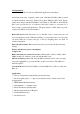
1.1 Introduction Intel® XScale®, Ultra Low Power, Embedded Applications Anywhere!! Advantech smart panel computers enable great embedded flexibility when powered by Intel® XScale® technology. Built with an Intel PXA255 CPU, LCD display, touchscreen, and pre-installed with Microsoft® Windows CE .NET 4.2 and LAN, the SPC series provide the best cost-effective and stable solution to customers for a diverse range of embedded applications.
1.2 Specifications There are 2 models of SPC-57 series, SPC-57E and SPC-57C. SPC-57C is the fully enclosure with standard external I/O connector. SPC-57E is without back cover, without standard external I/O connector, and without Flash memory on board. SPC-57E and SPC-57C can fulfill different applications and various demands from the customer. SPC-57C System kernel CPU Intel PXA-255 200MHz on board OS Windows CE .NET 4.
Power switch 1 power switch Power conn 1 power connector SW reset Through system configurator to execute the SW reset Mechanical Dimension 210 X 155 X 41 (mm) Material SPCC Certification CE, FCC class A, UL Environmental Operating temp 0 degree C ~ 50 degree C Storage temp -20 degree C ~ 60 degree C Water/dust resistance IP65 for front bezel SPC-57E System kernel CPU Intel PXA-255 200MHz on board OS Windows CE .NET 4.2 SDRAM 64MB SDRAM on board Flash N/A for SPC-57E.
Power V-in range DC 10V ~ 28V Protection Over current protection; Electric pole reverse protection SM bus For smart battery, pin headers Power switch 1 power switch Power conn 1 power connector SW reset Through system configurator to execute the SW reset Mechanical Dimension 210 X 155 X 41 (mm) Material SPCC Certification CE, FCC class A, UL Back cover Without back cover; without I/O board; Environmental Operating temp 0 degree C ~ 50 degree C Storage temp -20 degree C ~ 60 degree C Wa
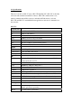
1.3 LCD Specifications LCD model Nan Ya LMB61-23 Display type STN color LCD Size (Diagonal) 5.7” Resolution 320 x 240 (VGA) Maximum colors 256 Pixel pitch (WxH, mm) 2 0.36 X 0.36 Luminance (cd/m ) 165 cd/m2 Contrast ratio 35 Response time Rise 300 ms, Fall 80 ms Lamp lifetime 20000 hours 1.
1.
1.
1.
CHAPTER 2 Getting Start This chapter provides brief instructions for operating the SPC-57
2.1 Quick Starting Step1: Unpack the SPC-57 from its packing. Please check the packing list at the beginning of this manual. Step2: Connect the power connector to 10 ~ 28 Vdc power source. The power source can either be from a power adapter or an in-house power source. Step3: Connect the power source to the system power supply. Step4: Plug in the power lines and turn on the system power switch, you will see the Welcome screen of Windows® CE.NET. Then you can start to use SPC-57.
Vcc GND 4. Plug the male power connector into female power connector in SPC.
5. Turn on the power switch 2.1.2 Supplying Power to SPC-57E 1. SPC accepts only DC power, not AC power 2. The DC input range for SPC is 10V ~ 28V. 3. Use the power cable (in SPC-57E package) to connect the board of SPC-57 and power source.
Power Connector Connect to the power source 4. If the power cable included in the SPC-57E package is not suitable to users’ application, users have to make their own cable to supply power to SPC.
CHAPTER 3 The Engine of the SPC-57 This chapter details hardware’s setting and functionality in the SPC-57 Sections include: • PCM-7230 SBC for SPC-57 • I/O Board • LCD and touch-screen • Power system
This chapter will detail hardware setting and functionality in the SPC-57. Following will introduce (1) PCM-7230 SBC for SPC-57; (2) The I/O Board (there is no I/O board of SPC-57E) (3) LCD and touch-screen; (4) Power system. 3.1 PCM-7230 Mainboard for SPC-57 The Engine of SPC-57 is constructed by the combination of 2 PCBA – one mainboard and one I/O board. The mainboard is slightly modified based on Advnatech standard product PCM-7230 to fulfill SPC-57 specification.
3.1.1 Specification Model PCM-7230 SBC for SPC-57 Model PCM-7230 SBC for SPC-57 CPU Kernel part Intel® PXA255 processor at 200 MHz System memory 1MB NOR flash for bootloader and 64MB SDRAM Memory Module N/A WDT PXA-255 Internal (2, 5, 10 Sec as default) RTC HT-1381 with rechargeable coin battery Power Input OS DC 10V~28V, with power protect (protect for over voltage, over current & short). Microsoft® Windows® CE.NET 4.
AC’97 Stereo Audio w/ 2W Amp. Audio - Line-In, Line-Out, Speaker-out and Mic-In SM Bus Backup Battery For sensing DC power and battery status. 2x2 2.00mm pin header For RTC On board : IO_VCC3P3 indicator(beside CN12), CF interface busy indicator(beside CN20). LED Indicator Pin header: SYS_VCC3P3, CF card busy indicator, PCMCIA card busy indicator, battery status indicator, LAN link, LAN speed 10/100 indicator.
Figure 3.
3.1.2 Headers and connectors This section locates headers and connectors of PCM-7230 and describes their functionality. CN3 JP1 CN1 CN8 CN12 CN10, CN11 CN14 J1 CN9 CN18 JP6 JP2 CN20 JP3 JP4 CN29 CN26 CN31 Figure 3.
Figure 3.3: Solder side of the PCM-7230 Table 3.
3.1.3 Headers and connectors pin definition Because the board size limitation & wants to keep the flexible of I/O connector placement, The following lists are I/O pin definitions of PCM-7230 SBC. All the pin headers’ pin order is the same as the figure. As you see, the first pin has a white mark on PCB. Except the pin headers, all the other connectors have white mark at 1st pin. 1 2 3 4 4 5 6 7 The following tables are the pin definition of all the connectors on PCM-7230 SBC.
★JP 3 : LCD signal voltage level select Pin Number 1 Pin function SYS_VCC Ps. +5V power of LCD-signal 2 LCD_VCC buffers +3.3V. VCC3P3 will 3 VCC3P3 change to 0V when system enter sleep mode. Note: when User wants to use CN18 (40 pin TTL level LCD signal) to drive LCD panel, user needs to setup this pin header. If the LCD panel signal is 3.3V then set the 2.00mm jumper at 1-2 pin of JP3; if the LCD panel signal is 5V then set the jumper at 2-3 pin.
17 18 19 20 21 22 23 24 25 26 27 28 DI 5* DO 5* DI 6* DO 6* DI 7* DO 7* GND VCC3P3 Digital input bit 5. Digital output bit 5. Digital input bit 6. Digital output bit 6. Digital input bit 7. Digital output bit 7.
the circuits. ★ CN 8 : CRT-out header Pin Number 1 2 3 4 5 6 7 8 Pin function Reserv. CRT _Vsync Reserv. CRT _Hsync CRT_B GND CRT _G CRT _R Ps. reserve for the future reserve for the future CRT blue signal CRT green signal CRT red signal ★ CN 9 : multi-function I/O header(II) Pin Number 1 2 3 4 5 Pin function TPTX100P TPTX100N TPRX100P TPRX100N RJ45_P4_P5 6 RJ45_P7_P8 7 8 9 10 11 12 13 14 15 16 17 Resv. Resv. Resv. Resv. Resv. Resv. Resv. Resv. Resv. Resv.
30 31 32 33 34 35 36 37 38 39 40 41 42 43 44 45 46 47 48 49 50 51 52 53 54 55 56 57 58 YP XN YN nUART1_DCD UART1_RXD UART1_TXD nUART1_DTR GND nUART1_DSR nUART1_RTS nUART1_CTS nUART1_RI VCC_UART1 GND VCC_UART1 N.C. N.C.
★CN 18 : TTL level LCD signal connector Pin Number Pin function 1 VCC 2 VCC 3 GND 4 GND 5 VCC3P3 6 VCC3P3 7 LCD_VEE 8 GND 9 LCD_D0 10 LCD_D1 11 LCD_D2 12 LCD_D3 13 LCD_D4 14 LCD_D5 15 LCD_D6 16 LCD_D7 17 LCD_D8 18 LCD_D9 19 LCD_D10 20 LCD_D11 21 LCD_D12 22 LCD_D13 23 LCD_D14 24 LCD_D15 25 LCD_D16 26 LCD_D17 27 LCD_D18 28 LCD_D19 29 LCD_D20 30 LCD_D21 31 LCD_D22 32 LCD_D23 33 GND 34 GND 35 SHCLK 36 FLM_VSYNC 37 M_DE 38 LP_HSYNC 39 N.C. 40 ENVEE note : User can use JP3 to change the LCD signals level.
★ CN 20 : LAN status LED header Pin Number Pin function Ps.
★CN 31 : SM bus port Pin Number Pin function 1 I2CSCL 2 GND I2CSDA 3 4 nDC_IN Ps. clock pin of SM bus for smart battery data pin of SM bus for smart battery This pin is pulled low on PCM-7230 by 2M ohm. 3.1.4 COM1~COM4 serial ports The PCM-7230 offers four full-functions RS-232 (COM1, COM2, and COM3) and one RS-485 w/ AFC (COM5) serial communication interface ports.
3.1.9 LCD inverter connector for 5V inverter(CN26, Pin1~Pin4) Connect the PCM-7230 with the 5V inverter for adjusting LCD panel’s brightness. The voltage range of this signal is from 0 to 5V. When enable backlight is on, the voltage of this signal is 5V; otherwise is 0V. Brightness voltage is adjustable by Advantech SW utility. 3.1.10 Audio connector(CN3,P25~P36) The PCM-7230 provides audio signals on pin25 ~ pin36 of CN3.
Figure 3.4: Component Side of Memory Module Figure 3.5 Solder side of Memory Module 3.1.16 Backup Battery (BT1) The PCM-7230 series build in one 3.0V, coin-type rechargeable backup battery for external RTC. This backup battery is charging when system power is on.
3.1.17 Form factor Figure 3.6 Form factor of the PCM-7230 3.2 I/O Board The I/O Board can expand its I/O function thru two I/O cables. The expand functions have RS-232*1(COM1); RS-485*1(COM4) ; Audio(Line-out) ; RJ-45 for Ethernet port ; USB Client ; 2 port USB Host ; Power connector (10~28 V) ; Power switch ; Power Source to main board ; Multi-function I/O header (I) ; Multi-function I/O header (II).
Figure 3.
Pin 1 Signal DCD 2 RXD 3 TXD 4 DTR 5 GND 6 DSR 7 RTS 8 CTS 9 RI Figure 3.
Pin Signal 1 N/C 2 Data+ 3 Data- 4 N/C 5 GND 6 N/C 7 N/C 8 N/C 9 N/C Figure 3.8 I/O Board COM4(RS-485) serial port ★ CN 2 : Audio (Line-out) port Pin Signal 1 Right channel 2 Left channel 3 GND 4 Left channel Figure 3.
Pin Signal 1 TPTX100P 2 TPTX100N 3 TPRX100P 4 N/C 5 N/C 6 TPRX100N 7 N/C 8 N/C 9 NC 10 NC 11 GND 12 GND 13 LED1+ 14 nLINK 15 LED2+ 16 nSPEED100 Figure 3.
Pin Signal 1 USB_VCC5 2 SA_BUSB_DNR 3 SA_BUSB_DPR 4 GND ripheral Board USB Client port Figure 3.11 I/O board USB client port ★ CN 1 : USB Host port Pin Signal 1 VCC_USB_H1 2 USB_N1 3 USB_P1 4 GND 5 VCC_USB_H2 6 USB_N2 7 USB_P2 8 GND F 3.
Pin Signal 1 19 VDC (+) 2 19 VDC (-) 3 GND Figure 3.12 I/O Board Power connector ★CN 10 : Power source to Main Board Pin Signal 1 GND 2 GND 3 DC in 4 DC in Figure 3.
Pin Number 1 2 3 4 5 6 7 8 9 10 11 12 13 14 15 16 17 18 19 20 Pin function UART1_RDCD UART1_RRXD UART1_RTXD UART1_RDTR GND UART1_RDSR UART1_RRTS UART1_RCTS UART1_RRI IO_VCC3P3 C950_485_RTXP C950_485_RTXN GND GND SPK_OUTRP SPK_OUTLP USB_VCC5 GND SA_BUSB_DPR SA_BUSB_DNR ★CN 8 : Multi-function I/O header (Il) 50 Ps.
Pin Number 1 2 3 4 5 6 7 8 9 10 11 12 13 14 15 16 17 18 19 20 Pin function AC97_AGND AC97_AGND TPRX100N TPRX100P TPTX100N TPTX100P nSPEED100 nLINK AC97_AGND AC97_AGND IO_VCC3P3 IO_VCC3P3 VCC_USB_H1 VCC_USB_H2 USB_P1 USB_N1 USB_P2 USB_N2 AC97_AGND AC97_AGND Ps. 3.3 Power system The power system of the SPC-57 includes IO board, adapter and power cord. Users can only use a Terminal Block 5.08mm 3P MALE 19Vdc power adapter to be SPC-57’s power input. There is one 3.
CHAPTER 4 Software Functionality This chapter details the Windows® CE.NET operating system on the Sections include: • Introduction •Windows® CE Startup Procedure • Upgrade Procedure • Utilities • Network • Intel Persistent Storage Manger • Application Program Development • Windows® CE.NET 4.
4.1 Introduction The SPC series is one embedded system with Windows® CE.NET OS. The Windows® CE.NET is a compact OS that occupies less storage space or system resources compared with other operating systems such as Windows® NT or Windows® XP. By its modular nature, it is possible to choose those functions that are useful for specific application. Not only reducing the system resources required, but also reduces start-up time.
want to Compact Flash card, and then load this image by BOOTLOADER. 2, Flexible Hardware design : Flash on board design is unnecessary. The Windows CE can be loaded by Compact Flash card. 4.3 Upgrade Procedure After the OS image was built, we may want to burn it to the on-board flash ROM. Advantech provides the upgrade utility “Upgrade” to upgrade Bootloader image, WinCE image or boot logo to onboard flash ROM. The upgrade procedure is described as following : Step1.
Figure 4.3 Upgrade utility Note: The difference between NK.NB0 (Compressed) and NK.NB0 (Normal, XIP) : The option “NK.NB0 (Normal, XIP)” means that the nk.nb0 will be upgraded directly to the flash ROM, and “NK.NB0 (Compressed)” means that we compress nk.nb0 first, and then write the compressed data to the flash ROM. : (1) Boot time : compressed image take more time in system bootup. (2) IPSM size : compressed OS image would result in larger IPSM size. Step4. Press ‘Apply’ button on the dialog.
Figure 4.5 Regflash utility It is important to keep the power normal during "Save to Flash" process. If the power were broken down during the registry saving process, then the registry would be lost and corrupted. On the next time you turn on platform, the system would load the default registry setting rather than the previously customized registry setting. 4.4.2 Reboot The utility "Reboot" is a convenient tool to reset the system. From the Windows® CE.NET status bar, tap "Start/Run".
there are two ways to perform "Starup" function. Method 1: Step1: Create "startup" directory in CF storage card or in folder "\IPSM\". Step2: Copy executable files to "startup" directory that is created by Step 1. Example: We copy two executable files "REGFLASH.exe" and "Notepad.exe" in "\IPSM\Startup", and then reboot the system. After the system boot up, the two executable files would automatically execute. Method 2: Step1: The same as Step1 in Method 1. Step2: Create a file called "startup.
4.4.5 System Configurator System Configurator is an outstanding utility designed by Advantech Windows® CE.NET software team. It is an integrated environment where user can get useful system information as well as configure favorite system settings and apply system control function on demand. Double click the icon of System Configurator on the desktop. Following sections illustrate the functions of System Configurator. 4.4.5.
Figure 4.8 Touch-screen calibration 4.4.5.3 Display From time to time it is unnecessary to turn on the display attached to the SPC all the day. The Display page provides several frequently used functions such as turning off the LCD and backlight to elongate the display repair period, adjusting brightness or contrast. For example, if user wants the backlight turn-off setting function, he can press "setting" button. Then the backlight page of Display Properties of Control Panel will appear on the screen.
4.4.5.4 WatchDog timer It is important in industrial applications that the control systems are rarely crashed, or are capable of self-reset if they are halted somehow. Watchdog function of automatic resetting system is therefore provided in SPC. There is a timer inside the watchdog function.
These settings can be freely revised by keying in new paths in the edit boxes. Figure 4.11 Hotkeys setting 4.4.5.6 DIO There are 8 digital inputs and 8 digital outputs. This DIO page of the System Configurator can show their status. When the “Start” button is pressed, the 8 DI will try to retrieve external inputs, then those pins having positive inputs will mark respective radial buttons inside the “Digital Input Status” block, others will make their radial buttons empty.
4.4.5.7 Miscellaneous The Misc page provides several functions as described below. The "Registry" block provides registry save and registry view function. The “A. Sync” button invokes ActiveSync to the host computer. ”The "HTTP Server Root" block was used to specify the root directory of http server. The default directory is "\windows\www\wwwpub", user can specify another directory by type the directory in the edit box and press "Set" button. The new setting would become effective after the system reboot.
4.5 Network 4.5.1 Networking via Ethernet SPC build in one 100Base-T Ethernet controller. It appears at “Control Panel/Network and Dial-up Connections” via “DM9CE1”. User can configure its Ethernet support as follows: 1. Click "Start/Settings/Control Panel" 2. Double click "Network and Dial-up Connections" 3. This window will display all available connections. Pressing the connection icon, its pop-up menu appears and users could disable, rename or modify properties from there. 4.
2. Connect the USB port of the host PC and the SPC by a USB ActiveSync cable. 3. If users are using the Microsoft eMbedded Visual Tools to develop Windows® CE.NET application runtimes, make sure the SPC SDK provided in the SPC support CD is also properly installed in the host PC. 4. Click "Start/Settings/Network and Dial-up Connections" 5. Make a new connection. As the dialogue box pops out, choose the default "Direct Connection" radial button. Click "Next". 6.
Figure 4.15 Networking via USB port 4.5.3 Networking via PPP The SPC supports PPP protocol. To setup and utilize it, follow the steps below: 1. Click "Start/Settings/Network and Dial-up Connections” 2. Make a new connection. As the dialogue box pops out, choose the "Dial-Up Connection". Click "Next". 3. Click "Configure" to setup the device according to the specification of your modem, and then click "OK" on the top-right corner of the window. 4. Click "Next".
Figure 4.16 Networking via PPP 4.5.4 Web browser The SPC builds-in Windows CE OS includes IE Browser. It can be used to browse web pages on World Wide Web via LAN or PPP.
4.6 Intel Persistent Storage Manger (IPSM) 4.6.1 Introduction to Intel Persistent Storage Manger Intel Persistent Storage Manager was designed and developed specifically as an enhancement to Microsoft Windows CE operating systems. IPSM eliminates extra disk-like storage such as storage cards, redundant RAM and ROM. 4.6.2 IPSM folder in SPC Series SPC uses Intel Persistent Storage Manger to utilize the free space of flash ROM for persistent storage.
4.7 Application Program Development The SPC is bundled with built-in Windows® CE.NET operating system. In real application user need to execute various application programs on it. However, unlike its other CPU family, the Windows® CE.NET is a hardware-dependent operating system. That is to say, Windows® CE.NET application programs are only portable in the source code level. Users must rebuild the runtime file for a different Windows® CE.NET platform even though the source code may not be changed at all. 4.
Figure 4.17 Flow-chart of Building Windows® CE.NET runtime 4.7.3 How to install SDK Copy SPC SDK file “SOM_A_SDK.msi” to your PC, and launch it. You can install SDK by steps. Step 1, Launch SPC SDK file, and then tap Next button. Figure 4.
Step 2, Accept License Agreement and go next. Figure 4.19 Step 3, Key in your information and go next.
Figure 4.20 Step 4, Choose setup type. There are 3 options “Embedded Visual C++”, “Microsoft .NET Compact Framework”, and “Documentation” in Custom Setup. Figure 4.
Figure 4.22 Step 5, Tap “Install” button to install SDK. Figure 4.
Install SDK……. Figure 4.24 Step6, Finish installing.
Figure 4.25 4.7.4 Running your application programs ActiveSync would automatically transfer the built application program to platform. Choose SDK type as SOM_A once compile your application program. Figure 4.26 4.7.5 WDT Modules SPC is targeted to be the embedded device for web-enabled and data-acquisition systems. It is built-in with a useful dynamic link library, WATCHDOG.
This function sends a control code directly to a specified device driver, causing the corresponding device to perform the specified operation. BOOL DeviceIoControl( HANDLE hDevice, DWORD dwIoControlCode, LPVOID lpInBuffer, DWORD nInBufferSize, LPVOID lpOutBuffer, DWORD nOutBufferSize, LPDWORD lpBytesReturned, LPOVERLAPPED lpOverlapped); - Parameters hDevice [in] Handle to the device that is to perform the operation. Call the Create- File function to obtain a device handle.
This parameter can be NULL if the dwIoControlCode parameter specifies an operation that does not produce output data. nOutBufferSize [in] Size, in bytes, of the buffer pointed to by lpOutBuffer. lpBytesReturned [out] Long pointer to a variable that receives the size, in bytes, of the data stored into the buffer pointed to by lpOutBuffer. The lpBytesReturned parameter cannot be NULL.
nInBufferSize: unused. lpOutBuffer: unused. nOutBufferSize: unused. 3. IOCTL_GET_WDTPERIOD (0x1003): lpInBuffer :unused. nInBufferSize: unused. lpOutBuffer: the DWORD pointer to your Watchdog time setting. The unit is mini-second. Its value should be greater 1000. The default setting is 5000 mini-seconds. nOutBufferSize: unused. 4. IOCTL_SET_WDTPERIOD (0x1004): lpInBuffer : the DWORD pointer to your Watchdog time setting. Its value should be greater 1000. The unit is mini-second.
lpOutBuffer: the DWORD pointer to your screen off time if user-interface idled. The unit is mini-second. If the value is 0, screen-off function is disabled. nOutBufferSize: unused. 7. IOCTL_SET_SCREENOFFTIME (0x1007): lpInBuffer : the DWORD pointer to your screen off time if user-interface idled. The unit is mini-second. If the value is 0, screen-off function is disabled. nInBufferSize:unused. lpOutBuffer: unused. nOutBufferSize: unused. 8. IOCTL_SET_SCREENOFF (0x1010): Set the LCD power off immediately.
HANDLE m_hWDT=NULL; TCHAR szClassName[60]; ... // assign the WDT driver name wsprintf(szClassName, TEXT("WDT1:")); // Open the WDT driver m_hWDT = CreateFile(szClassName, GENERIC_READ | GENERIC_WRITE, 0, NULL, OPEN_EXISTING, FILE_ATTRIBUTE_NORMAL, NULL); if ( m_hWDT == INVALID_HANDLE_VALUE ) { DebugMsg(CString("WDT driver fail")); return; } ...
4.8 Windows® CE.NET 4.2 Require Components (Advantech Recommend) Applications and Services Development (■: with; □: without) Feature Active Template Library (ATL) C Libraries & Runtimes Component Services (COM) Device Management Lightweight Directory Access Protocol (LDAP) Message Queuing (MSMQ) Microsoft Foundation Classes (MFC) Object Exchange Protocol (OBEX) Pocket Outlook Object Model (POOM) API Simple Object Access Protocol (SOAP) Toolkit Standard SDK for Windows CE .NET .
■ Kernel Features Communication Services and Networking Feature Networking Features Networking - Local Area Network (LAN) Networking - Personal Area Network (PAN) Networking - Wide Area Network (WAN) Servers (HTTPD) Default Selection ■ ■ ■ ■ ■ File Systems and Data Store Feature Storage Manager File & Database Replication (Bit-based) File System – Internal (RAM & ROM File System) Registry Storage (RAM-based Registry) Default Selection ■ ■ ■ ■ Fonts Default Selection Feature Arial Comic Sans MS Courie
Locale Specific Support (Input Method Selector Sample Application) Multilingual User Interface (MUI) ■ ■ Internet Client Services Default Selection Feature Browser Application (Internet Explorer 5.5 for Windows CE ■ Standard Components) Internet Explorer 5.
Shell and User Interface Default Selection Feature Shell User Interface - Accessibility - Customizable UI - Mouse - Touch Display (Stylus) - Network User Interface - Overlapping Menus - Software Input Panel - Speech Interface ■ ■ ■ ■ ■ ■ ■ ■ ■ ■ 83
Appendix A Boot & Registry Searching Sequence The following diagram demonstrates the boot sequence and registry searching sequence when SPC boot-up.