
User manual


Table Of Contents
- Chapter 1 Overview
- Chapter 2 Hardware Functionality
- 2.1 Introduction
- 2.2 RS-232/422/485 Interface (COM1~COM2)
- 2.3 Optional RS-232 Interfaces (COM3~COM4)
- 2.4 LAN: Ethernet Connector
- 2.5 Power Inputs
- 2.6 USB Connector
- 2.7 DVI-I Display Connector
- 2.8 Reset Button
- 2.9 Power Button
- 2.10 Audio
- Chapter 3 Initial Setup
- Appendix A System Settings and Pin Assignments
- A.1 System I/O Address and Interrupt Assignments
- A.2 Board Connectors and Jumpers
- A.3 RS-232 Standard Serial Port (COM3~COM4)
- A.4 RS-232/422/485 Serial Port (COM1~COM2)
- A.5 Ethernet RJ-45 Connector (LAN1~LAN2)
- A.7 PS/2 Keyboard and Mouse Connector
- A.8 USB Connector (USB1~USB4 & CN7)
- A.9 VGA Display Connector
- Appendix B Programming the Watchdog Timer
UNO-3072LA User Manual 16
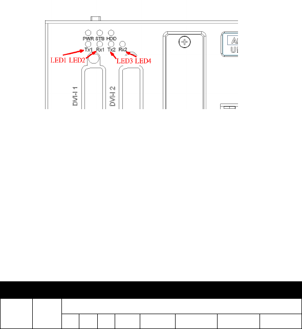
Figure 2.5: Programmable LED
In order to use programmable LED, user needs to change BIOS setting to
switch the LED for COM port Tx & Rx to programmable LED function.
Please follow the steps below:
1. Boot up or reset the system, press Del to enter into BIOS
2. Select Integrated Peripherals
→ Onboard Device → LED Select,
Default setting is "Comport TX-RX", change the setting to "Pro-
grammable LED".
3. Press F10 or Back to "Save and Exit Setup" to finish setup change.
(Please install DI/O driver from the UNO CD to use these example)
Table 2.2: LED Control Register
212H R/W Diagnostic / Programmable LED Register
x x x x P1 P2 P3 P4
Note: Px: = 0, DIAG LED disable
= 1, DIAG LED enable
Note: UNO-3072LA provides built-in examples to show how to con-
figure DIAG LED and Buzzer. Refer to console mode exam-
ples in C:\Program
Files\Advantech\UNO\UNO_IsaDIO\Examples\Console.