IPPC-9120G Rugged Industrial Panel PC with Intel® Pentium® III or Celeron® and 12.
Copyright notice This document is copyrighted 2001, by Advantech Co. Ltd. All rights are reserved. Advantech Co., Ltd. reserves the right to alter the products described in this manual at any time without notice. No part of this manual may be reproduced, copied, translated or transmitted in any form or by any means without the prior written permission of Advantech. Information provided in this manual is intended to be accurate and reliable.
FCC Class B This equipment has been tested and found to comply with the limits for a Class B digital device, pursuant to Part 15 of the FCC Rules. These limits are designed to provide reasonable protection against harmful interference when the equipment is operated in a residential environment. This equipment generates, uses and can radiate radio frequency energy. If not installed and used in accordance with this user's manual, it may cause harmful interference to radio communications.
Packing List Before setting up the system, check that the item is among those listed below and is in good condition. If your Panel PC does not match any of those below, please contact your dealer immediately. The IPPC-9120G and IPPC-9150G Series of Industrial Panel PCs includes the following models: 1. IPPC-9120G Rugged industrial panel PC with Intel Pentium III or Celeron with 12.1” TFT LCD Display 2. IPPC-9120G-R IPPC-9120G with resistive type touchscreen 3.
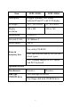
Item IPPC-9120G IPPC-9150G Description Rugged Pentium® III/Celeron Industrial Panel PC with LCD display LCD type 12.
Additional Information and Assistance Step 1. Visit the Advantech web site at www.advantech.com where you can find the latest information about the product. Step 2. Contact your distributor, sales representative, or Advantech's customer service center for technical support if you need additional assistance.
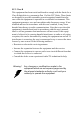
Safety Instructions 1. Read these safety instructions carefully. 2. Keep this User's Manual for later reference. 3. Disconnect this equipment from any AC outlet before cleaning. Use a damp cloth. Do not use liquid or spray detergents for cleaning. 4. For plug-in equipment, the power outlet socket must be located near the equipment and must be easily accessible. 5. Keep this equipment away from humidity. 6. Put this equipment on a reliable surface during installation.
Wichtige Sicherheishinweise 1. Bitte lesen sie Sich diese Hinweise sorgfältig durch. 2. Heben Sie diese Anleitung für den späteren Gebrauch auf. 3. Vor jedem Reinigen ist das Gerät vom Stromnetz zu trennen. Verwenden Sie Keine Flüssig-oder Aerosolreiniger. Am besten dient ein angefeuchtetes Tuch zur Reinigung. 4. Die NetzanschluBsteckdose soll nahe dem Gerät angebracht und leicht zugänglich sein. 5. Das Gerät ist vor Feuchtigkeit zu schützen. 6.
Der arbeitsplatzbezogene Schalldruckpegel nach DIN 45 635 Teil 1000 beträgt 70dB(A) oder weiger. Haftungsausschluss: Die Bedienungsanleitungen wurden entsprechend der IEC-704-1 erstellt. Advantech lehnt jegliche Verantwortung für die Richtigkeit der in diesem Zusammenhang getätigten Aussagen ab.
IPPC-9120G/9150G Users Manual x
Contents Chapter 1 General Information ........................................2 1.1 1.2 Introduction ....................................................................... 2 Specifications .................................................................... 3 1.2.1 1.2.2 1.2.3 1.2.4 1.2.5 1.2.6 1.2.7 1.2.8 1.3 General............................................................................ 3 Standard PC Functions.................................................... 3 PCI SVGA/Flat Panel Interface...
2.6.2 Chapter Figure 2.11:Mounting the IPPC-9120G/9150G Series into a Frame ...................................................... 22 Rack Mounting ............................................................. 23 Figure 2.12:Mounting the IPPC-9120G/9150G Series into a Frame ...................................................... 23 Figure 2.13:Mounting the IPPC-9120G/9150G Series and Frame Assembly into a Rack............................ 24 3 Jumper Settings & Connectors .....................26 3.
5.2 Installation of Ethernet Driver......................................... 46 5.2.1 5.3 Chapter 6 VGA Setup ......................................................52 6.1 Introduction ..................................................................... 52 6.1.1 6.1.2 6.1.3 6.2 6.3 Installation for Windows 95/98/ME ............................. 53 Installation for Windows NT ........................................ 55 Further Information .........................................................
Appendix C Pin Assignments ...........................................118 C.1 AT Power connector (J1)) ............................................. 118 C.2 TV Output Connector (J11) (*Reserved) ...................... 118 C.3 Inverter Power Connector (J4) ...................................... 119 C.4 Internal Speaker Connector (J6) (*Reserved) ............... 119 C.5 Front Panel Control Connector (J8) (*Reserved)......... 120 C.6 IR Connector (J9) (*Reserved) ....................................
Table C.23:COM1 RS-232 serial port (CN14)........... 134 C.21 Parallel port (CN9) ........................................................ 135 C.22 Keyboard & PS/2 Mouse connector (CN22)................. 135 Table C.24:Parallel port (CN9)................................... 135 Table C.25:USB1/USB2 (CN19/CN20) .....................
IPPC-9120G/9150G Users Manual xvi
CHAPTER 1 General Information This chapter gives background information on IPPC-9120G and IPPC-9150G.
Chapter 1 General Information 1.1 Introduction IPPC-9120G and IPPC-9150G series of industrial panel PCs are especially designed to fit in space-limited environments where expansion is restricted. Its solid structure enables the systems to operate under harsh industrial conditions. Sturdy structure The whole system is protected by a firm solid structure. The front panel is made of sturdy aluminum and has strengthened glass. It is shock resistant, and complies with NEMA4/IP65.
1.2 Specifications 1.2.1 General • Dimensions (W x H x D): 402 x 302 x 127 mm (15.94" x 11.88" x 5") • Weight: 10 kg (22 lb) • Power supply: 100 W • Input voltage: 115 V AC / 3 A ~ 230 V AC / 1.5 A @ 47 ~ 63 Hz • Output voltage: +5 V @ 15 A, +12 V @ 5 A, -12V @ 0.5A • Cooling fan dimensions (W x H x D): Two fans that both measure 60 x 60 x 10 mm (2.36" x 2.36" x 0.39"). • Disk drive housing: Supports one 2.5" HDD, one slim size CD-ROM drive. • Chassis: Aluminum front frame complies with NEMA4/IP65.
• Serial ports: Four serial ports with three RS-232 ports (COM1, COM3, and *COM4) and one RS-232/422/485 port (COM2). All ports are compatible with 16C550 UARTs • Universal serial bus (USB) port: Supports up to two USB (version 2.0) ports • PCI/ISA bus expansion slot: Two expansion slots for either two PCI cards or one PCI card and one ISA card. • Watchdog timer: 62-level, interval 1 ~ 62 seconds. Automatically generates system reset or IRQ11 when the system stops due to a program error or EMI.
• Audio interface: Microphone-in, line-in, line-out, and game ports. Warning *COM port 4 on the IPPC-9120G-R,and IPPC9150G-R models are reserved for a touchscreen only. Improper use of this COM port will cause system failure. 1.2.5 PCI bus Ethernet Interface • Chipset: Realtek RTL 8139 PCI local bus Ethernet controller • Ethernet Interface: Fully complies with IEEE 802.3u 100Base-T and 10 Base-T specifications. Includes software drivers and boot ROM • 100/10Base-T auto-sensing capability 1.2.
1.2.7 Optional Accessories • IPPC-9150GStand: stand kit for IPPC-9150G and IPPC-9120G series products • IPPC-9150GS-ARM: swing arm for IPPC-9150G and IPPC-9120G series • IPPC-9150GRack-MT: 19" rank mounint kit for IPPC-9150G and IPPC-9120G Series • CDR-9150-24X: 24x CD-ROM kit for IPPC-9150G and IPPC-9120G series 1.2.
1.3 Dimensions 12 ” Figure 1.1: IPPC-9120G Front View 15 ” Figure 1.
17 ” Figure 1.
CHAPTER 2 System Setup This chapter details system setup for the IPPC-9120G and IPPC-9150G Series. Sections include: • General • Installing SDRAM • Installing a CPU • Installing a 2.
Chapter 2 System Setup 2.1 A Quick Tour of IPPC-9120G and IPPC-9150G Before you start the computer, please follow these procedures to set up the system. 1. Check and adjust jumpers on the motherboard (see Chapter 3) 2. Install SDRAM 3. Install a CPU 4. Install add-on cards 5. Connect the wires, cables and accessories 6. Mount the computer 7. Program the BIOS settings 8. Install an operating systeml. Warnings 1. Switch off and unplug the computer every time you access its interior. 2.
Figure 2.1: Side View • Backdoor Lock Backdoor Knob Add-on Card Bay Cover • • USB Port x 2 Ethernet Port • • • • • • •• • • • Power cord lock bracket • • 4 COM Ports VGA Port Brightness Control Audio ports Parallel Port PS/2 Keyboard / Mouse Connector Game Port Figure 2.
2.1.1 PS/2 mouse and keyboard If you wish to use a full-size desktop keyboard and PS/2 mouse with your panel PC, follow these instructions: 1. Be sure the panel PC is turned off. 2. Connect the Y-shaped adapter to the PS/2 mouse and keyboard port on the rear bottom side of the rear cover. 3. Attach the keyboard to the 5-pin port of the Y-shaped adapter. 4. Attach the PS/2 mouse to the 6-pin female PS/2 port of the Y-shaped adapter. 5. Turn on the panel PC. 2.1.
2.1.3 Serial COM ports There are four serial COM ports on the bottom of the rear cover. You can easily attach a serial device to the panel PC, such as an external modem or mouse. Follow these instructions: 1. Make sure the panel PC and any other peripherial devices you may have connected to the panel PC are turned off. 2. Attach the interface cable of the serial device to the panel PC's serial port. (See Fig. 2-2.) If necessary, attach the other end of the interface cable to your serial device.
2.1.6 Audio interface The audio interface includes three jacks: microphone-in, line-out and line-in. Their functions are: Microphone-in: Use an external microphone to record voice and sound. Line-out:Output audio to external devices such as speakers or earphones. The built-in speaker will not be disabled when the line-out jack is connected to external audio devices. Line-in: Input audio from an external CD player or radio. 1. Connect the audio device to the system. 2.
2.2 Installing SDRAM You can install from 128 to 512 MB (x2) of SDRAM memory. The Panel PC system provides one 168-pin DIMM (Double Inline Memory Module) socket, and supports 3.3 V SDRAM with a minimum speed of 12 ns. 1. Unlock the back door and open it. 2. Push the two white eject levers on each side of the DIMM outward until they are separated from the black vertical posts. 3. Insert the memory module into the socket at an angle of 90 degrees. 4.
2.3 Installing a CPU The CPU can be upgraded to improve system performance. The system provides Socket 370 architecture which supports Pentium® III CPU up to 1.26 GHz, and Celeron up to 1.3 GHz..l. Warnings Always disconnect the power cord from your panel PC when you are working on it. Do not make connections while the power is on, because sensitive electronic components can be damaged by the sudden rush of power. Only experienced electronics personnel should open the panel PC. 1.
Figure 2.4: Installing a CPU Figure 2.
2.4 Installing a 2.5" HDD You can attach one enhanced Integrated Device Electronics (IDE) hard disk drive to IPPC-9120G/9150G's internal controller which uses PCI local bus interface. The advanced IDE controller supports faster data tranfer and allows the IDE hard drive to exceed 528 MB. The following instructions are for installation: 1. Unlock the back door and open it. 2. Unscrew the bolt in the center of the HDD-CDR kit (see figure 2.6). 3. Detach the CD-ROM flat cable. 4.
Figure 2.6: Removing the Back Case Screws Figure 2.
Figure 2.8: Adding Anti-shock Sponges to the HDD Figure 2.
2.5 Installing Add-on Cards This system supports two PCI cards or one PCI and one ISA expansion card. 1. Detach the five screws on the back to open the lid. 2. Take away the adapter bracket by detaching the screw which is mounted in the little box (see Fig. 2-10). 3. Insert the add-on card, and put on the lid. Figure 2.
2.6 Mounting Instructions There are two ways to mount the system: panel mounting or rack mounting. 2.6.1 Panel Mounting 1. Take the four mounting brackets out of the accessory box. 2. Attach the four mounting brackets by inserting the screws into the keyhole slots on the cover of the monitor. 3. Use the screws to secure the brackets to the cover. Tighten the screws to secure the monitor to the back panel. Figure 2.
2.6.2 Rack Mounting The monitor can be mounted to a 19" industrial rack with an optional bracket. If you wish to order this bracket, please refer the sales representative to "IPPC-9150GRack-MT". Mount the monitor to the bracket by following the instructions in Section 2.7.1 on the previous page. Then attach the bracket with the monitor to the 19" industrial rack. (See Fig. 2-12.) Figure 2.
Figure 2.
CHAPTER 3 Jumper Settings and Connectors This chapter tells how to set up the panel PC hardware, including instructions on setting jumpers and connecting peripherals, switches and indicators. Be sure to read all the safety precautions before you begin the installation procedures.
Chapter 3 Jumper Settings & Connectors 3.1 Jumpers and Connectors 3.1.1 Setting jumpers You can configure your panel PC to match the needs of your application by setting jumpers. A jumper is the simplest kind of electrical switch. It consists of two metal pins and a small metal clip (often protected by a plastic cover) that slides over the pins to connect them. To “close” a jumper, you connect the pins with the clip. To “open” a jumper you remove the clip.
3.1.2 Jumpers and switch The motherboard of the IPPC-9120G/9150G has a number of jumpers that allow you to configure your system to suit your applications. The table below lists the function of each of the board’s jumpers. Table 3.
3.1.3 Connectors Onboard connectors link the panel PC to external devices such as hard disk drives or floppy drives. The table below lists the function of each of the board’s connectors. JP2: LAN power type selection JP1: Internal -12V source selection setting SW1: Panel type setting JP6: COM2 RS232/422/485 setting JP4: Clear CMOS JP5: COM1/COM2 /COM3/COM4 pin 9 output type setting JP3: Watchdog timer action Figure 3.
Table 3.
3.1.4 Locating connectors J4: Inverter power connector J1: AT power connector FAN2: System fan power connector J8: Front panel control connector J6: Internal speaker connector Slot1: PCI/ISA expansion slot FAN1: CPU fan power connector CN18: CD-ROM connector CN16: EIDE hard disk drive connector CN10: Floppy drive connector CN3: Flat panel display connector CN2: Flat panel display connector CN27: Touchscreen interface & PS/2 connector J9: IR connector Figure 3.
3.3 CMOS Clear for External RTC (JP4) This jumper is used to erase CMOS data and reset system BIOS information. The procedure for clearing CMOS is: 1. Turn off system. 2. Short pin 2 and pin 3. 3. Return jumper to pins 1 and 2. 4. Turn on the system. The BIOS is now reset to its default setting. Table 3.
3.4 COM-port interface (JP5, JP6) The panel PC provides four serial ports (COM1, 3, 4: RS-232; COM2: RS-232/422/485) in one COM port connector. 3.4.1 COM2 RS-232/422/485 setting (JP6) COM2 can be configured to operate in RS-232, RS-422, or RS-485 mode. This is done via JP6. Table 3.
request IRQ is IRQ4: and COM2's address range is 2F8 ~ 2FF and its interrupt IRQ is IRQ3. COM3 and COM4 are another set. Their selectable function is the same as the COM1/COM2 set. Table 3.5: Serial port default settings Port Address Range Interrupt COM1 3F8 ~ 3FF IRQ4 COM2 2F8 ~ 2FF IRQ3 COM3 3E8 ~ 3EF IRQ10 COM4 2E8 ~ 2EF IRQ5 3.4.2 COM1/2/3/4 pin 9 output setting (JP5) Table 3.
3.5 VGA interface The panel PC's AGP VGA interface can drive conventional CRT displays. It is also capable of driving a wide range of flat panel displays, including electroluminescent (EL), gas plasma, passive LCD and active LCD displays. 3.5.1 LCD panel power setting The panel PC's AGP SVGA interface supports 5 V and 3.3 V LCD displays. The LCD cable already has a built-in default setting. You do not need to adjust any jumper or switch to select the panel power. 3.
3.7 Wake on LAN select (JP2) The IPPC-9120G/9150G provides Wake-on LAN function when ATX power is used. To enable Wake-on LAN function, the JP2 should be set as shown below: Table 3.8: Wake-on-LAN select (JP2) *Normal Power Wake-on-LAN * default setting 3.8 Internal -12 V Source Selection Setting (JP1) The panel PC provides an internal -12 V source in an expansion slot, available for various expansion card applications. Table 3.
IPPC-9120G/9150G Users Manual 36
CHAPTER 4 VIA Chipset This chapter provides information on VIA chipset configuration.
Chapter 4 VIA Chipset 4.1 Introduction The IPPC-9120G/9150G uses the chipset PN133T (codename: Twister) from VIA Technologies, Inc., built-in high performance 2D/3D Savage4 graphics, flexible 66/100/133MHz system bus settings, support for PC100/133 SDRAM and multiple power saving modes make the VIA PN133 the ideal integrated SMA chipset for the Intel Pentium® III, Intel® Celeron. and VIA C3 processor.
4.2.1 Installation for Windows 98/NT/2000/ME 1. a. Select "Start", "Run”. b. Enter the driver path "D:\IPPC-9120G 9150G DRV & Utility\VIA4in1\Setup.exe". c. Click “OK”. 2. a. Press "Next" to continue the installation.
3. a. Press "Yes" to accept the agreement." 4.
5. Click “Next” 6. a.
7. Click “Next”. 8. Click “Next”.
9. Click "Finish" to reboot the system. 4.3 Further Information For further information about the AGP/VGA installation in your IPPC9120G/9150G, including driver updates, troubleshooting guides and FAQ lists, visit the following web resources: VIA website: www.via.com.tw Advantech websites: www.advantech.com www.advantech.com.
IPPC-9120G/9150G Users Manual 44
CHAPTER 5 PCI Bus Ethernet Interface This chapter provides information on Ethernet configuration.
Chapter 5 PCI Bus Ethernet Interface 5.1 Introduction The IPPC-9120G/9150G is equipped with a high performance 32-bit Ethernet chipset, which is fully compliant with IEEE 802.3 100 Mbps CSMA/CD standards. It is supported by major network operating systems. It is also both 100Base-T and 10Base-T compatible. The Ethernet port provides a standard RJ-45 jack. The network boot feature can be utilized by incorporating the boot ROM image files for the appropriate network operating system.
5.2.1 Installation for Windows 98/NT/ME/2000 1. a. Select "Start", "Run" b. Enter the path: "D:\IPPC-9120G 9150G DRV & Utility\LAN\setup.exe" c. Click "OK" 2. a. Click "Next".
3. a. Select "Search for the best driver for your device. (Recommended)" b. Click "Next" 4. a.
5. a. Click "Next" 6. a. Click "Next" 7. a. Type the path "D:\IPPC-9120G 9150G DRV & Utility\LAN\WIN98" b.
Note: 1. Installation for Windows 95, please type the path “D:\IPPC-9120G 9150G DRV & Utility\LAN\WIN95A” 2. Installation for Windows 95osr2, please Type the path “D:\IPPC-9120G 9150G DRV & Utility\LAN\W95OSR2" 3. Installation for Windows ME, please Type the path "D:\IPPC-9120G 9150G DRV & Utility\LAN\WINME" 4. Installation for Windows NT/2000, please type the path "D:\IPPC-9120G 9150G DRV & Utility\LAN\WIN2000" 5.
CHAPTER 6 2 VGA Setup This chapter provides information on the VGA setup.
Chapter 6 VGA Setup 6.1 Introduction The IPPC-9120G/9150G has an onboard AGP flat panel/VGA interface. The specifications and features are described as follows: 6.1.1 Chipset The IPPC-9120G/9150G uses a VIA Twister 8606T chipset from VIA Technology Inc. for its controller. It supports many popular LCD, and LVDS LCD displays and conventional analog CRT monitors. The VIA8606T VGA BIOS supports color TFT and DSTN LCD flat panel displays.
6.2 Installation of the VGA Driver Complete the following steps to install the VGA driver. Follow the procedures in the flow chart that apply to the operating system that you are using within your IPPC-9120G/9150G. 6.2.1 Installation for Windows 95/98/ME 1. a. Select "Start", "Run" b. Enter the path D:\IPPC-9120G 9150G DRV & Utility\VGA\Win9X_ME\setup.exe Notes: 1. Installation for Windows 2000, please Type the path “D:\IPPC-9120G 9150G DRV & Utility \VGA\Win2000\setup.exe" 2.
3. Click "Next" 4.
6.2.2 Installation for Windows NT 1. From "Start", select the "Settings group", then click on the "Control Panel" icon. 2. In the "Control Panel", double click on the "Display" icon. 3. In the "Settings" screen, click on the "Display Type..." button. 4. From the "Display Type" screen, and in the "Adapter Type" section, click on the "Change..." button. 5. In the "Change Display" screen, click on the "Have Disk..." button. 6.
6.3 Further Information For further information about the AGP/VGA installation in your IPPC9120G/9150G, including driver updates, troubleshooting guides and FAQ lists, visit the following web resources: VIA website: www.via.com.tw Advantech websites: www.advantech.com www.advantech.com.tw After installing the VGA driver under Win 98, if you want to play a VCD, please install Directx 8.1 (or higher) which you can find at www.microsoft.com.
CHAPTER 7 Audio Setup This chapter provides information on the Audio setup.
Chapter 7 Audio Setup 7.1 Introduction The IPPC-9120G/9150G's on-board audio interface provides high-quality stereo sound and FM music synthesis (ESFM) by using the VIA VT82C686 audio controller from VIA. The audio interface can record, compress, and play back voice, sound, and music with built-in mixer control. The IPPC-9120G/9150G on board audio interface also supports the Plug and Play (PnP) standard and provides PnP configuration for the audio, FM, and MPU-104 logical devices.
7.2.1 Installation for Windows 98/ME/2000/XP 1. a. Select "Start", "Run" b. Enter the path "D:\IPPC-9120G 9150G DRV & Utility \Audio\Win98_ME_2000__XP\setup.exe" Notes: 1. Installation for Windows 95, please type the path " D:\IPPC-9120G 9150G DRV & Utility \Audio\Win95\setup.exe" 2. Installation for Windows NT, please Type the path "D:\IPPC-9120G 9150G DRV & Utility \Audio\WinNT\setup.exe" 2.
IPPC-9120G/9150G Users Manual 60
CHAPTER 2 8 Touchscreen This chapter contains information on the touchscreen, its installation and configuration.
Chapter 8 Touchscreen 8.1 Introduction The FPM-2150G Series’ optional touchscreen uses advanced 8-wire resistive technology. It provides more accurate sensing capacity than other technologies. The touchscreen is specially designed for tough industrial environments, and has been approved to FCC Class B standards. 8.2 Touchscreen Specifications Electrical • Contact bounce: < 10 ms • Operating voltage: 5 V (typical) • Sheet Resistance: 350 +/- 22% per Square. • Linearity: <1.
Optical • Visible light transmission: 75% typical (>74% @ 550 nm test) • Clarity: Clear Finish - 25%, Antiglare Finish - 15% Sensor board • Chemical strengthened glass with 4 H hardness standard. (Test condition: ASTM D3363-92A) Ball drop test • Able to bear a 225 g steel ball dropped from 660 mm elevation without breaking Environmental Specifications • Operating Temperature Range: -20° C ~ +50° C, 2 weeks at 50° C / 90% RH. • Storage Temperature High: +70° C, 240 hours at ambient humidity.
Before installing the Windows 2000/XP driver software, you must have the Windows 2000/XP system installed and running on your computer. You must also have one of the following PenMount Serial Interface controller boards installed: 90A4, 9026B, 9036 or 9084. Contents of the PenMount Windows 2000/XP driver folder are listed below. DMC9000.inf DMC9000.sys DMC9000.cat SETUP.EXE If you have an older version of the PenMount Windows 2000/XP driver installed in your system, please remove it first.
2. Insert the PenMount Driver CD-ROM. Go to: "D:\TouchScreen-DRV\ Penmount 9000(resistive)\Windows 2000-XP Driver V4.01". Click setup.exe. 3. The screen displays the installation wizard for the PenMount software. Click “Next”.
4. A License Agreement appears. Click “I accept…” and “Next” 5. The “Ready to Install the Program” screen appears. Select “Install.
6. The next screen is “Hardware Installation.” Select “Continue Anyway.” 7. The “InstallShield Wizard Completed” appears. Click “Finish.
8.4 Configuring PenMount Windows 2000/XP Driver Upon rebooting, the computer automatically finds the new 9000 controller board. The touch screen is connected but not calibrated. Follow the procedures below to carry out calibration. 1. After installation, click the PenMount Monitor icon “PM” in the menu bar. 2. When the PenMount Control Panel appears, click “Calibrate.” 8.4.
NOTE: The older the touch screen, the more Advanced Mode calibration points you need for an accurate calibration. Use a stylus during Advanced Calibration for greater accuracy.
IPPC-9120G/9150G Users Manual 70
Plot Calibration Data Check this function and a touch panel linearity comparison graph appears when you have finished Advanced Calibration. The blue lines show linearity before calibration and black lines show linearity after calibration.
Draw Tests or demonstrates the PenMount touch screen operation. The display shows touch location. Click Draw to start. Touch the screen with your finger or a stylus and the drawing screen registers touch activity such left, right, up, down, pen up, and pen down. Touch the screen with your finger or a stylus and the drawing screen registers touch activity such left, right, up, down, pen up, and pen down. Click Clear Screen to clear the drawing.
Multiple Monitors Multiple Monitors supports from two to six touch screen displays for one system. The PenMount drivers for Windows 2000/XP support Multiple Monitors. This function supports from two to six touch screen displays for one system. Each monitor requires its own PenMount touch screen control board, either installed inside the display or in a central unit. The PenMount control boards must be connected to the computer COM ports via the RS-232 interface.
2. When the mapping screen message appears, click OK. 3. Touch each screen as it displays “Please touch this monitor.” Following this sequence and touching each screen is called mapping the touch screens.
4. Touching all screens completes the mapping and the desktop reappears on the monitors. 5. Select a display and execute the ‘Calibration’ function. A message to start calibration appears. Click OK. 6. “Touch this screen to start its calibration” appears on one of the screens. Touch the screen. 7. “Touch the red square” messages appear. Touch the red squares in sequence. 8. Continue calibration for each monitor by clicking Standard Calibration and touching the red squares.
NOTE: 1. If you used a single VGA output for multiple monitors, please do not use the Multiple Monitors function. Just follow the regular procedure for calibration on each of your desktop monitors. 2. The Rotating function is disabled if you use the Multiple Monitors function. 3. If you change the resolution of display or screen address, you have to redo Map Touch Screens so the system understands where the displays are.
About This panel displays information about the PenMount controller and driver version.
8.4.2 PenMount Monitor Menu Icon The PenMount monitor icon (PM) appears in the menu bar of Windows 2000/XP system when you turn on PenMount Monitor in PenMount Utilities. PenMount Monitor has the following functions. Beep Turns beep on or off. Right Button When you select this function, a mouse icon appears in the right-bottom of the screen. Click this icon to switch between Right and Left Button functions.
8.4.3 PenMount Rotating Functions The PenMount driver for Windows 2000/XP supports several display rotating software packages. Please see Chapter 5 for more information.
8.5 Uninstall the PenMount Windows 2000/XP driver 1. Exit the PenMount monitor (PM) in the menu bar. 2. Go to Settings, then Control Panel, and then click Add/Remove program. Select PenMount DMC9000 and click the Add/Remove button. 3. Select PenMount DMC9000 and DMC9100. Click the Remove button. 4. Select ‘Yes’ and “Close” to remove the PenMount Windows 2000/ XP driver, and reboot the system.
CHAPTER 9 PCMCIA Sections include: • Introduction • Installation of PCMCIA driver for Windows 95
Chapter 9 PCMCIA 9.1 Introduction The IPPC-9120G/9150G is equipped with a high performance PCMCIA interface which complies with the 1995 PCMCIA card standard by using the RICOH Cardbus controller. The panel PC supports two PCMCIA card/cardbus slots. Two sockets support both a 16-bit PCMCIA card and a 32-bit Cardbus simultaneously, with hot insertion and removal. 9.
9.2.1 Installation for Windows 95 1. a. In "Start", "Run", type the path: "D:\IPPC-9120G 9150G DRV & Utility \Cardbus\win95osr2\setup.exe" 2. a. Click "Next" to continue the installation. 3. a. Click "Yes".
4. Click "Finish" to reboot the system.
CHAPTER 10 Award BIOS Setup This chapter describes how to set BIOS configuration data
Chapter 10 Award BIOS Setup 10.1 Award BIOS Setup The IPPC-9120G/9150G comes with an Award BIOS chip that contains the ROM setup for your system. This chip serves as an interface between the processor and the rest of the mainboard's components. This chapter explains the information contained in the setup program and tells you how to modify the settings according to your system configuration. Some setup items will not be explained, because it is recommended that users do not change such items.
Frequency/Voltage Control Load Optimized Defaults Set Password Save & Exit Setup Exit without Saving Standard CMOS Features Advanced BIOS Features Advanced Chipset Features Integrated Peripherals Power Management Setup PnP/PCI Configurations ↑ ↓ → ← : Select Item Esc : Quit F10 : Save & Exit Setup Time, Date, hard disk Type… 10.2.1 Standard CMOS Setup Standard CMOS Setup records some basic system hardware configuration and sets the system clock and error handling.
2. Use one of the arrow keys to move between options and modify the selected options by using PgUp / PgDn / + / - keys. Date (mm:dd:yy) The BIOS determines the day of the week from the other date information. This field is for information only. Press the left or right arrow key to move to the desired field (date, month, year). Press the PgUp or PgDn key to increment the setting, or type the desired value into the field. Time (hh:mm:ss) The time format is based on the 24-hour military-time clock.
Drive A / Drive B Select this field to the type(s) of floppy disk drive(s) installed in your system. The choices are: 360 KB, 5.25 in; 1.2 MB, 5.25 in; 720 KB, 3.5 in; 1.44 MB, 3.5 in; 2.88 MB, 3.5 in; None. Video Select the type of primary video subsystem in your computer. The BIOS usually detects the correct video type automatically. The BIOS supports a secondary video subsystem, but you do not select it in setup.
Base Memory Typically 640KB. Also called conventional memory. The DOS operating system and conventional applications use this area. Extended Memory Above the 1MB boundary. Early IBM personal computers could not use memory above 1MB, but current PCs and their software can use extended memory. Total Memory This option shows system memory capacity. 3. Press to return to the Main Menu when you finish setting up all items. 10.
Virus Warning CPU Internal Cache External Cache CPU L2 Cache ECC Checking Processor Number Feature Quick Power On Self Test First Boot Device Second Boot Device Third Boot Device Boot Other Device Swap Floppy Drive Boot Up Floppy Seek Boot Up NumLock Status Gate A20 Option Typematic Rate Setting Typematic Rate (Chars/Sec) Typematic Delay (Msec) Security Option PS/2 Mouse Function OS Select For DRAM > 64MB Reports No FDD For Win95 Video BIOS Shadow C8000-CBFFF Shadow CC000-CFFFF Shadow D0000-D3FFF Shadow D40
CPU Internal Cache/External Cache Cache memory is additional memory that is much faster than conventional DRAM (system memory). CPUs from 486-type up contain internal cache memory, and most, but not all, modern PCs have additional (external) cache memory. When the CPU requests data, the system transfers the requested data from the main DRAM into cache memory, for faster access by the CPU.
Gate A20 Option Gate A20 refers to the way the system addresses memory above 1 MB (extended memory). When set to Fast, the system chipset controls Gate A20. When set to Normal, a pin in the keyboard controller controls Gate A20. Setting Gate A20 to Fast improves system speed, particularly with OS/2 and Windows. Typematic Rate Setting When Disabled, the following two items (Typematic Rate and Typematic Delay) are irrelevant. Keystroke repeats at a rate determined by the keyboard controller in your system.
C8000-CBFFF to DC000-DFFFF Shadow These options are used to shadow other expansion card ROMs. Small Logo (EPA) show 3. Press to return to the Main Menu when you finish setting up all items. 10.4 Advanced Chipset Features Advanced Chipset Features is used to modify the values of chipset buffers. These buffers control the system options. Run the Advanced Chipset Features as follows: 1. Choose “Advanced Chipset Features” from the Main Menu and a list of options will appear.
DRAM Clock This item allows you to control the DRAM speed. The choices are : Host Clock, HCLK+33M. SDRAM Cycle Length Select CAS latency time in HCLKs of 2 or 3. The system designer already set the values. Do not change the default value unless you change specifications of the installed DRAM or the installed CPU. Bank Interleave Please use default setting. The choices: Disabled; 2 Bank; 4 Bank. Memory Hole In order to improve performance, certain space in memory is reserved for ISA cards.
AGP Driving Control This item allows you to adjust the AGP driving force. Choose Manual to key in a AGP Driving Value in the next selection. This field is recommended to set in Auto for avoiding any error in your system. The choice: Manual, Auto. AGP Driving Value This item allows you to adjust the AGP driving force. The choice: Min=0000 ~ Max=00FF. Boot Device Select This item allows you to select your boot display device.
PCI Delay Transaction Leave this field at default. The choice: Enabled, Disabled. PCI Master 0 WS Write When Enabled, writes to the PCI bus are executed with zero wait states. The choice: Enabled, Disabled. PCI # 2 Access # 1 Retry Leave this field at default. The choice: Enabled, Disabled(default). AGP Master 1 WS Write Leave this field at default. The choice: Enabled, Disabled(default). AGP Master 1 WS Read Leave this field at default. The choice: Enabled, Disabled(default).
On-Chip IDE Channel 0 Enabled On-Chip IDE Channel 1 Enabled IDE Prefetch Mode Enabled Primary Master PIO Auto Primary Slave PIO Auto Secondary Master PIO Auto Secondary Slave PIO Auto Primary Master UDMA Auto Primary Slave UDMA Auto Secondary Master UDMA Auto Secondary Slave UDMA Auto Init Display First PCI Slot IDE HDD Block Mode Enabled Onboard FDD Controller Enabled Onboard Serial Port 1 Auto Onboard Serial Port 2 Auto UART 2 Mode Standard IR Function Duplex Half TX, R
Primary Master / Slave PIO & Secondary Master / Slave PIO Choose Auto or Mode 0~4. The BIOS will detect the HDD mode type automatically when you choose Auto. You need to set to a lower mode than Auto when your hard disk becomes unstable. The choices: Auto; Mode 0; Mode 1; Mode 2; Mode 3; Mode 4.
IR Function Duplex This item allows you to select the IR half / full duplex function. The choices: Half; Full. TX, RX inverting enable This item allows you to enable the TX, RX inverting which depends on different H/W requirement. This field is not recommended to change its default setting. The choices: “No, No”; “No, Yes”; “Yes, No”; “Yes, Yes”. Onboard Parallel Port Select a logical LPT port name and matching address for the physical parallel (printer) port.
10.6 Power Management Setup POWER MANAGEMENT SETUP allows you to set the system’s power saving functions. Run the POWER MANAGEMENT SETUP as follows: 1. Choose“Integrated Peripherals”from the Main Menu and a list of options will appear. 2. Use one of the arrow keys to move between options and modify the selected options by using PgUp / PgDn / + / - keys.
• Power Management: This option allows you to select the type (or degree) of power saving for Doze, Standby, and Suspend modes. This table describes the power management modes for your reference: Max Saving User Define Min Saving Maximum power savings. Only Available for SL CPUs. Inactivity period is 1 minute in each mode. Set each mode individually. Select time-out period in the section for each mode stated below. Minimum power savings. Inactivity period is 1 hour in each mode (except the hard drive).
Video Off Method This determines the manner in which the monitor is blanked. V/H SYNC + Blank Blank Screen DPMS Supports This selection will cause the system to turn off the vertical and horizontal synchronization ports and write blanks to video buffer. This option only writes blanks to the video buffer. Select this option if you monitor supports the Display Power Management Signaling (DPMS) standard of the Video Electronics Standards to select video power management values.
• Primary INTR: When set to on, any event occurring at will awaken a system which has been powered down. On(default):The system can not enter the power saving mode when I/O ports or IRQ# is activated. Off:The system still can enter the power saving mode when I/O ports or IRQ# is activated. • IRQ Activity Monitoring: The following is a list of IRQ’s (Interrupt Requests), which can be exempted much as the COM ports and LPT ports above can.
10.7 PnP/PCI Configuration PnP/PCI Configuration allows you to modify the system’s power saving functions. Run the PnP/PCI Configuration as follows: 1. Choose“PnP/PCI Configuration”from the Main Menu and a list of options will appear. 2. Use one of the arrow keys to move between options and modify the selected options by using PgUp / PgDn / + / - keys.
IRQ Resources Press Enter. Please refer to the list below: IR Q - 9 a s s i g n e d to P C I/ IS A P n P Ite m H e lp M e n u L e ve l DMA Resources Press Enter. Please refer to the below list.
3. Press to return to the Main Menu when you finish setting up all items. 10.8 PC Health Status This section helps you to get more information about your system including CPU temperature, FAN speed and voltage. It is recommended that you contact your mainboard supplier to get proper values about the setting of the CPU temperature. Run the PC Health Status as follows: 1. Choose“PC Health Status”from the Main Menu and a list of options will appear. 2.
10.9 Frequency/Voltage Control Run the Frequency/Voltage Control as follows: 1. Choose“Frequency/Voltage Control”from the Main Menu and a list of options will appear. 2. Use one of the arrow keys to move between options and modify the selected options by using PgUp / PgDn / + / - keys.
10.11 Set Password These option allows you to set your system passwords. The way to set up the password is as follows: 1. Choose “Change Password” in the Main Menu and press . Then following message appears: “Enter Password : “ 2. The first time you run this option, enter your password up to 8 characters and press . (The screen does not display the entered characters.) 3.
10.12 Save & Exit Setup Save & Exit Setup allows you to save all modifications you have specified into the CMOS memory. Highlight this option on the Main Menu and the following message appears: “Save to CMOS and Exit (Y/N) ? Y “ “Y” is for “Yes”, and “N” is for “No”. Press key to save the configuration changes. 10.13 Exit Without Saving Exit Without Saving option allows you to exit the Setup Utility without saving the modifications that you have specified.
Appendix A LCD Specifications and Selection Settings
Appendix A LCD Specifications Table 1: IPPC-9120G/9150G Series LCD Specifications IPPC-9120G IPPC-9150G Display 12.1" TFT LCD 15" TFT LCD Max. resolution 800 x 600 1024 x 768 Colors 262 K Dot pitch (mm) 0.31 x 0.31 0.29 x 0.29 Viewing angle 100° (H), 60° (V) 120° (H),100° (V) Luminance 320 cd/sq meter 250 cd/sq meter Viewing area 246 x 184.5 mm Power consumption 304 x 228 mm 3.3 V @ 0.25 A Operating temperature 3.
Appendix B Programming the Watchdog Timer The IPPC-9120G/9150G is equipped with a watchdog timer that resets the CPU or generates an interrupt if processing comes to a standstill for any reason. This feature ensures system reliability in industrial standalone or unmanned environments.
Appendix B Programming the Watchdog Timer B.1 Programming the Watchdog Timer To program the watchdog timer, you must write a program which writes I/ O port address 443 (hex). The output data is a time interval value. The value range is from 01 (hex) to 3E (hex), and the related time interval is from 1 sec. to 62 sec. Data Time Interval 01 1 sec. 02 2 sec. 03 3 sec. 04 4 sec. • • • • • • 3E 62 sec.
The following example shows how you might program the watchdog timer in BASIC: 10 REM Watchdog timer example program 20 OUT &H443, data REM Start and restart the watchdog 30 GOSUB 1000 REM Your application task #1, 40 OUT &H443, data REM Reset the timer 50 GOSUB 2000 REM Your application task #2, 60 OUT &H443, data REM Reset the timer 70 X=INP (&H443) REM, Disable the watchdog timer 80 END 1000 REM Subroutine #1, your application task • • • • • • 1070 RETURN 2000 REM Subroutine #2, you
IPPC-9120G/9150G Users Manual 116
Appendix C I/O Pin Assignments • AT Power Connector (J1) • TV Output Connector (J11) (*Reserved) • Inverter Power Connector (J4) • Internal Speaker Connector (J6) (Reserved) • Front Panel Control Connector (J8) (Reserved) • IR Connector (J9) (Reserved) • Flat Panel Display Connector (CN2) • Flat Panel Display Connector (CN3) • Floppy Drive Connector (CN10) • EIDE Hard Disk Drive Connector (CN16) • CD-ROM Connector (CN18) • CPU Fan Power Connector (FAN1) • System Fan Power Connector (FAN2) • PCI/ISA Expans
Appendix C Pin Assignments C.1 AT Power connector (J1)) Table C.1: Table D-1: AT power connector (J1) Pin Signal 1 2 3 4 5 6 7 8 9 10 11 12 PS_NO # +5 VSB +12 V -12 V GND GND GND GND -5 V +5 V +5 V +5 V 12 1 C.2 TV Output Connector (J11) (*Reserved) Table C.
C.3 Inverter Power Connector (J4) Table C.3: Inverter power connector (J4) Pin 1 2 3 4 5 1 2 3 4 5 Signal +12 V GND ENABKL Brightness Adj. +5 V C.4 Internal Speaker Connector (J6) (*Reserved) 1 2 3 4 Table C.
C.5 Front Panel Control Connector (J8) (*Reserved) Table C.5: Front panel control connector (J8) Pin 1 2 3 4 5 6 Signal Vcc GND HDD LED Reset SW Power SW GND 6 5 4 3 2 1 C.6 IR Connector (J9) (*Reserved) 1 2 3 4 5 Table C.
C.7 Flat Panel Display Connector (CN2) Table C.
C.8 Flat Panel Display Connector (CN3) Table C.
C.9 Floppy Drive Connector (CN10) Table C.
C.10 EIDE Hard Disk Drive Connector (CN16) 43 41 3 1 44 42 4 2 Table C.
C.11 CD-ROM Connector (CN18) Table C.
C.12 CPU Fan Power Connector (FAN1) 1 2 3 Table C.12: CPU fan power connector (FAN1) Pin 1 2 3 Signal GND +12 V FAN_DET D.14 System Fan Power Connector (FAN2) C.13 Fan power connector (FAN2) 3 2 1 Table C.
C.
Table C.
Table C.
Table C.
Table C.
C.15 Touchscreen Connector (CN23) Table C.18: Internal COM4 and PS/2 Conn. (CN23) Pin Signal Pin Signal 1 3 5 7 9 11 13 15 NRLSD NRX NTX NDTR GND MSDAT MSCLK +5V 2 4 6 8 10 12 14 16 NDSR NRTS NCTS NRI GND EXT MSDAT EXT MSCLK +5V C.16 COM1 RS-232 serial port (CN11) Table C.
C.17 COM2 (CN12) Table C.20: COM2 (CN12) Pin Signal RS-422 RS-485l 1 2 3 4 5 6 7 8 9 DCD RX TX DTR GND DSR RTS CTS RI (RI/+5V/+12V TXTX+ RX+ RXGND DATADATA+ C.18 COM3 RS-232 serial port (CN13) Table C.
C.19 COM4 RS-232 serial port (CN14) Table C.22: COM1 RS-232 serial port (CN14) Pin Signal Pin Signal 1 3 5 7 9 DCD TxD GND RTS RI (RI/+5V/+12V 2 4 6 8 RXD DTR DSR CTS C.20 Keyboard & PS/2 Mouse connector (CN22) Pin 6 Pin 5 Pin 4 Pin 3 Pin 2 Pin 1 Table C.
C.21 Parallel port (CN9) 1 2 3 4 5 6 7 8 910 11 12 13 14 15 16 17 18 19 20 21 22 23 24 25 Table C.24: Parallel port (CN9) Pin Signal Pin Signal 1 3 5 7 9 11 13 15 17 19 21 23 25 Strobe D1 D3 D5 D7 BUSY SLCT ERR SLTCTINI GND GND GND GND 2 4 6 8 10 12 14 16 18 20 22 24 D0 D2 D4 D6 ACK PE AUTOFD INIT GND GND GND GND C.22 Keyboard & PS/2 Mouse connector (CN22) Table C.
IPPC-9120G/9150G Users Manual 136