IPPC-9120/9150 Series Rugged Pentium®III/Celeron™ Industrial panel PC with 12.
Copyright notice This document is copyrighted 2001, by Advantech Co. Ltd. All rights are reserved. Advantech Co., Ltd. reserves the right to alter the products described in this manual at any time without notice. No part of this manual may be reproduced, copied, translated or transmitted in any form or by any means without the prior written permission of Advantech. Information provided in this manual is intended to be accurate and reliable.
FCC Class B This equipment has been tested and found to comply with the limits for a Class B digital device, pursuant to Part 15 of the FCC Rules. These limits are designed to provide reasonable protection against harmful interference when the equipment is operated in a residential environment. This equipment generates, uses and can radiate radio frequency energy. If not installed and used in accordance with this user's manual, it may cause harmful interference to radio communications.
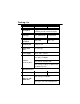
Packing List Before setting up the system, check that the items listed below are included and in good condition. If any item does not accord with the table, please contact our dealer immediately. The IPPC-9120/9150 Series industrial panel PCs include the following models: 1. IPPC-9120T Rugged Pentium®III/Celeron™ industrial panel PC with 12.1” TFT LCD 2. IPPC-9120T-T IPPC-9120T with resistive type touchscreen 3. IPPC-9150T Rugged Pentium®III/Celeron™ industrial panel PC with 15” TFT LCD 4.
Packing List Item IPPC-9120T IPPC-9150T Description Rugged Pentium® III/Celeron™ industrial panel PC with LCD display LCD type 12.1" TFT SVGA 15" TFT XGA Display resolution 800 x 600 Motherboard PCM-9571B Floppy disk drive 3.
Additional Information and Assistance 1. Visit the Advantech websites at www.advantech.com or www.advantech.com.tw, where you can find the latest information about the product. 2. Contact your distributor, sales representative, or Advantech's customer service center for technical support if you need additional assistance.
Safety Instructions 1. Read these safety instructions carefully. 2. Keep this User's Manual for later reference. 3. Disconnect this equipment from any AC outlet before cleaning. Use a damp cloth. Do not use liquid or spray detergents for cleaning. 4. For plug-in equipment, the power outlet socket must be located near the equipment and must be easily accessible. 5. Keep this equipment away from humidity. 6. Put this equipment on a reliable surface during installation.
Wichtige Sicherheishinweise 1. Bitte lesen sie Sich diese Hinweise sorgfältig durch. 2. Heben Sie diese Anleitung für den späteren Gebrauch auf. 3. Vor jedem Reinigen ist das Gerät vom Stromnetz zu trennen. Verwenden Sie Keine Flüssig-oder Aerosolreiniger. Am besten dient ein angefeuchtetes Tuch zur Reinigung. 4. Die NetzanschluBsteckdose soll nahe dem Gerät angebracht und leicht zugänglich sein. 5. Das Gerät ist vor Feuchtigkeit zu schützen. 6.
Contents Chapter 1 General Information 1 1.1 Introduction ............................................................................2 1.2 Specifications .......................................................................3 General .................................................................................... Standard PC functions ............................................................... PCI SVGA/flat panel interface ..................................................... Audio function ......
2.7.2 Rack mounting ................................................................. 26 Chapter 3 Jumper Settings and Connectors 29 3.1 Jumpers and Connectors ..................................................30 3.1.1 Setting jumpers ................................................................ 30 3.1.2 Jumpers and switch.......................................................... 31 3.1.3 Locating jumpers and switch ............................................. 32 3.1.4 Connectors ......................
5.2 Installation of SVGA Driver ................................................54 5.2.1 Installation for Windows 95 ................................................ 56 5.2.2 Installation for Windows 98 ................................................ 59 5.2.3 Installation for Windows NT ............................................... 62 5.3 Further Information .............................................................65 Chapter 6 Audio 67 6.1 Introduction ............................................
9.4 9.5 9.6 9.7 9.8 9.9 9.10 9.11 9.12 9.13 9.14 BIOS Features Setup ...................................................... 109 Chipset Features Setup ..................................................113 Power Management Setup .............................................115 PNP/PCI Configuration Setup ........................................118 Load BIOS Defaults .........................................................119 Load Setup Defaults .......................................................
C.14 CPU Fan Power Connector (FAN1) .............................. 142 C.15 System Fan Power Connector (FAN2) ......................... 142 C.16 PCI/ISA Bus Expansion Connector (SLOT1) ............... 143 C.17 COM2 ...............................................................................
Figures Figure 1-1: IPPC-9120 front view ............................................................... 7 Figure 1-2: IPPC-9150 front view ............................................................... 7 Figure 1-3: IPPC-9120/9150 Series dimensions ......................................... 8 Figure 2-1: Side view .............................................................................. 11 Figure 2-2: Rear view ..............................................................................
Tables Table 3-1: Jumpers and their functions ................................................. 31 Table 3-2: Panel PC connectors .......................................................... 33 Table 3-3: COM2 RS-232/422/485 setting (JP3, JP4) ............................. 35 Table 3-4: COM2 RS-232/422/485 setting (JP5) .................................... 35 Table 3-5: Serial port default settings ................................................... 36 Table 3-6: COM1 / COM2 pin 9 output type setting (JP9) ..
CHAPTER 1 General Information • Introduction • Specifications • Dimensions
1.1 Introduction The IPPC-9120/9150 series industrial panel PC is specially designed to fit in space-limited environments where expansion is restricted. Its solid structure enables the system to operate under harsh industrial conditions. Sturdy structure The whole system is protected by a firm solid structure. The front panel is made of sturdy aluminum and has strengthened glass. It is shock resistant, and complies with NEMA4/IP65.
1.2 Specifications General • Dimensions (W x H x D): 405 x 302 x 127 mm (15.94" x 11.88" x 5") • Weight: 10 kg (22 lb) • Power supply: 80 watts Input voltage: 115 V AC / 3 A ~ 230 V AC / 1.5 A @ 47 ~ 63 Hz Output voltage: +5 V @ 12 A, +12 V @ 1 A • Cooling fan dimensions (W x H x D): 60 x 60 x 10 mm (2.36" x 2.36" x 0.39") • Disk drive housing: Supports one 2.5" HDD, one slim size CD-ROM drive, and one slim type FDD • Chassis: Aluminum front frame complies with NEMA4/IP65.
• Serial ports: Four serial ports with three RS-232 ports (COM1, COM3, and *COM4) and one RS-232/422/485 port (COM2). All ports are compatible with 16C550 UARTs • Universal serial bus (USB) port: Supports up to two USB ports • PCI/ISA bus expansion slot: Accepts either two PCI cards or one ISA/one PCI bus card • Watchdog timer: 63-level, interval 1 ~ 63 seconds. Automatically generates system reset or IRQ11 when the system stops due to a program error or EMI.
PCI bus Ethernet interface • Chipset: Realtek RTL 8139 PCI local bus Ethernet controller • Ethernet interface: Fully complies with IEEE 802.3u 100Base-T and 10 BaseT specifications.
Environmental • Operating temperature: 0° ~ 50° C (32° ~ 122° F) • Storage temperature: -20° ~ 60° C (-4° ~ 140° F) • Relative humidity: 10 ~ 90% @ 40° C (non-condensing) • Shock: 30 G peak acceleration (11 ms duration) • Power MTBF: 100,000 hrs • Certification: CE, FCC Class A; meets UL, BSMI 6 IPPC-9120/9150 Series User's Manual
1.
Figure 1-3: IPPC-9120/9150 Series dimensions 8 IPPC-9120/9150 Series User's Manual
CHAPTER System Setup • General • Installing SDRAM • Installing a CPU • Installing a 2.
2.1 A Quick Tour of the IPPC-9120/9150 Series Before you start the computer, please follow these procedures to set up the system. 1. Check and adjusting jumpers on the motherboard (refer to Chapter 3) 2. Installing SDRAM 3. Installing a CPU 4. Installing add-on cards 5. Connect the wires, cables and accessories 6. Mounting the computer 7. Programming BIOS settings 8. Installing an operating system Warnings: 1. Every time you access the interior of the computer, please switch it off and unplug it. 2.
2.5" HDD Slim type 1.
2.1.1 PS/2 mouse and keyboard If you wish to use a full-size desktop keyboard and PS/2 mouse with your panel PC, follow these instructions: 1. Be sure the panel PC is turned off. 2. Connect the Y-shaped adapter to the PS/2 mouse and keyboard port on the rear bottom side of the rear cover. 3. Attach the keyboard to the 5-pin port of the Y-shaped adapter. 4. Attach the PS/2 mouse to the 6-pin female PS/2 port of the Y-shaped adapter. 5. Turn on the panel PC. 2.1.
2.1.3 Serial COM ports There are four serial COM ports on the bottom of the rear cover. You can easily attach a serial device to the panel PC, such as an external modem or mouse. Follow these instructions: 1. Make sure the panel PC and any other peripherial devices you may have connected to the panel PC are turned off. 2. Attach the interface cable of the serial device to the panel PC's serial port. (See Fig. 2-2.) If necessary, attach the other end of the interface cable to your serial device.
2.1.5 USB ports An external USB device may be connected to the system via the 4-pin USB ports located on the rear side of the system unit. 1. Connect the external device to the system. 2. The USB ports support hot plug-in connection. You should install the device driver before you use the device. 2.1.6 Audio interface The audio interface includes three jacks: microphone-in, line-out and line-in. Their functions are: Microphone-in: Use an external microphone to record voice and sound.
2.2 Installing SDRAM You can install from 32 to 256 MB of SDRAM memory. The panel PC system provides one 168-pin DIMM (Double Inline Memory Module) socket, and supports 3.3 V SDRAM with a minimum speed of 12 ns. 1. Unlock the back door and open it. 2. Push the two white eject levers on each side of the DIMM outward until they are separated from the black vertical posts. 3. Insert the memory module into the socket at an angle of 90 degrees. 4.
2.3 Installing a CPU The CPU can be upgraded to improve system performance. The system provides Socket 370 architecture which supports Pentium® III CPU up to 850 MHz, Celeron™ up to 700 MHz. Warning: Always disconnect the power cord from your panel PC when you are working on it. Do not make connections while the power is on, because sensitive electronic components can be damaged by the sudden rush of power. Only experienced electronics personnel should open the panel PC. 1.
Figure 2-4: Installing a CPU Chapter 2 System Setup 17
2.4 Installing a 2.5" HDD The system supports one 2.5" slim type IDE HDD. The IDE controller, which uses a PCI local bus interface, allows the HDD to exceed 528 MB. When installing an HDD, follow these steps: 1. Unlock the back door and open it. 2. Unscrew the bolt in the center of the HDD-FDD bracket. 3. Detach the FDD flat cable. 4. Remove the five screws on the back case (see Fig. 2-5). 5. Take out the HDD-FDD bracket. 6. Remove the four screws in the bottom of the HDD-FDD bracket (see Fig.
Figure 2-5: Removing the back case screws Chapter 2 System Setup 19
Figure 2-6: Removing the HDD/FDD bracket screws 20 IPPC-9120/9150 Series User's Manual
Figure 2-7: Assembling the HDD 2.5 Installing a CD-ROM Drive One slim type CD-ROM drive can be installed in the system. Before installing the CD-ROM drive, take out the FDD-HDD bay. (Refer to Section 2.4) 1. Remove the three screws on the bottom of back case (see Fig. 2-8). 2. Pull out the drive bay cage, and attach the CD-ROM drive's cable to connector CN18 on the motherboard. 3. Install "CDR-9150-24X" into the drive bay by inserting it directly into the end. Then attach the cable to the CD-ROM drive. 4.
Figure 2-8: Removing the back case screws Figure 2-9: Attaching the connector to the CD-ROM 22 IPPC-9120/9150 Series User's Manual
2.6 Installing Add-on Cards This system supports two PCI cards or one PCI and one ISA expansion card. 1. Detach the five screws on the back to open the lid. 2. Take away the adapter bracket by detaching the screw which is mounted in the little box (see Fig. 2-10). 3. Insert the add-on card, and put on the lid.
2.7 Mounting Instructions There are two ways to mount the system: panel mounting or rack mounting. 2.7.1 Panel mounting 1. Take the four mounting brackets out of the accessory box. 2. Attach the four mounting brackets by inserting the screws into the keyhole slots on the cover of the monitor. 3. Use the screws to secure the brackets to the cover. Tighten the screws to secure the monitor to the back panel.
Figure 2-11: Panel mounting Chapter 2 System Setup 25
2.7.2 Rack mounting The monitor can be mounted to a 19" industrial rack. Please order the optional bracket "IPPC-9150 Rack-MT". Mount the monitor to the bracket by following the instructions in Section 2.7.1 on the previous page. Then attach the bracket with the monitor to the 19" industrial rack. (See Fig. 2-12.
Figure 2-13: Mounting the IPPC-9120/9150 Series and frame assembly into a rack Chapter 2 System Setup 27
28 IPPC-9120/9150 Series User's Manual
CHAPTER 3 Jumper Settings and Connectors This chapter tells how to set up the panel PC hardware, including instructions on setting jumpers and connecting peripherals, switches and indicators. Be sure to read all the safety precautions before you begin the installation procedures.
3.1 Jumpers and Connectors 3.1.1 Setting jumpers You can configure your panel PC to match the needs of your application by setting jumpers. A jumper is the simplest kind of electrical switch. It consists of two metal pins and a small metal clip (often protected by a plastic cover) that slides over the pins to connect them. To “close” a jumper, you connect the pins with the clip. To “open” a jumper you remove the clip. Sometimes a jumper will have three pins, labeled 1, 2, and 3.
3.1.2 Jumpers and switch The motherboard of the IPPC-9120/9150 has a number of jumpers that allow you to configure your system to suit your applications. The table below lists the function of each of the board’s jumpers.
3.1.
3.1.4 Connectors Onboard connectors link the panel PC to external devices such as hard disk drives or floppy drives. The table below lists the function of each of the board’s connectors.
3.1.
3.2 CPU Installation You can install a Pentium® III CPU up to 850 MHz or Celeron ™ CPU up to 700 without setting any frequency ratio or voltage. 3.3 COM-port Interface The IPPC-9120/9150 provides four serial ports (COM1, 3, 4: RS-232; COM2: RS-232/422/485) in one COM port connector. 3.3.1 COM2 RS-232/422/485 setting (JP3, JP4, JP5) COM2 can be configured to operate in RS-232, RS-422, or RS-485 mode. This is done via JP3, JP4 and JP5.
However, if you wish to disable the port or change these parameters later you can do this in the system BIOS setup. The table overleaf shows the default settings for the panel PC’s serial ports. COM1 and COM2 are one set. You can exchange the address range and interrupt IRQ of COM1 for the address range and interrupt IRQ of COM2. After exchanging, COM1's address range is 2F8 ~ 2FF and its request IRQ is IRQ3: and COM2's address range is 3F8 ~ 3FF and its interrupt IRQ is IRQ4. COM3 and COM4 are another set.
3.3.3 COM3 / COM4 pin 9 output type setting (JP6) Table 3-7: COM3/RI pin setting (JP6) *Normal operation +5 V output +12 V output 6 5 6 5 6 5 4 3 4 3 4 3 2 1 2 1 2 1 * default setting Note: Pins 1, 3 and 5 are for COM3. Pins 2, 4 and 6 are for COM4. 3.4 CMOS Clear for External RTC (JP8) Warning: To avoid damaging the computer, always turn off the power supply before setting “Clear CMOS”. Set the jumper back to “Normal operation” before turning on the power supply.
3.5 Internal -12 V Source Enable Setting (JP1) The panel PC provides an internal -12 V source to the expansion slots. Table 3-9: Internal -12 V source enable setting (JP1) * Enable -12 V support 1 2 Disable -12 V support 1 2 * default setting 3.6 VGA Interface The Panel PC's AGP VGA interface can drive conventional CRT displays. It is also capable of driving TFT and DSTN LCD displays.
cation for a special purpose, we recommend that you consult your distributor or our sales representative for detailed information. Table 3-10: Panel type select (SW3) Panel type Pin1 Pin2 Pin3 Pin4 Pin5 Pin6 Pin7 Pin8 800 x 600 3.
40 IPPC-9120/9150 Series User's Manual
CHAPTER 4 PCI Bus Ethernet Interface This chapter provides information on Ethernet configuration.
4.1 Introduction The IPPC-9120/9150 is equipped with a high performance 32-bit Ethernet chipset which is fully compliant with IEEE 802.3 100 Mbps CSMA/CD standards. It is supported by major network operating systems. It is also both 100Base-T and 10Base-T compatible. The medium type can be configured via the RSET8139.exe program included on the utility disk. The Ethernet port provides a standard RJ-45 jack.
4.2.1 Installation for Windows 95 1. a. Select "Start," "Settings," "Control Panel," "System" b. Click "Device Manager" and "Other Devices" c. Remove "PCI Ethernet Controller" item 2. a. Select "Start," "Settings," "Control Panel" and "Network" b.
3. Select "Adapter" and then "Add" 4. Press the "Have Disk..." button 5. a. Type path "D:\IPPC9150&9120T\Lan\W95OSR2" b.
6. a. Choose "Realtek RTL8139(A/B/C/8130)PCI Fast Ethernet" b. Press "OK" 7. a. Press "Add..." to select suitable services or protocol b. Press "OK" to finish network configuration 8.
4.2.2 Installation for Windows 98 1. a. Select "Start," "Settings," "Control Panel," "System" b. Click "Device Manager" and "Other Devices" c. Remove "PCI Ethernet Controller" item 2. a. Select "Start," "Settings," "Control Panel" and "Network" b.
3. Select "Adapter" and then "Add" 4. Press the "Have Disk..." button 5. a. Type path "D:\IPPC950&9120T\LAN\WIN98" b.
6. a. Choose "Realtek RTL8139(A/B/C/8130)PCI Fast Ethernet" b. Press "OK" 7. a. Press "Add..." to select suitable services or protocol b. Press "OK" to finish network configuration 8.
4.2.3 Installation for Windows NT 1. a. Select "Start," "Settings," "Control Panel" and double click the "Network" icon b. Choose "Adapters" tab c. Click "Add" 2. Press "Have Disk...
3. a. Enter the path "D:\IPPC9150&9120T\LAN\Winnt4" b. Press "OK" 4. a. Choose "Realtek RTL8139(A/B/C/8130)PCI Fast Ethernet" b. Press "OK" 5.
6.
4.3 Further Information Realtek website: www.realtek.com.tw Advantech websites: www.advantech.com www.advantech.com.
CHAPTER PCI SVGA Setup • Introduction • Installation of SVGA Driver - for Windows 95 - for Windows 98 - for Windows NT • Further Information 5
5.1 Introduction The IPPC-9120/9150 has an onboard AGP flat panel/VGA interface. The specifications and features are described as follows: 5.1.1 Chipset The IPPC-9120/9150 uses a Lynx3DM chipset from Silicon Motion Inc. for its AGP/SVGA controller. It supports TFT, DSTN flat panel dispays and conventional analog CRT monitors. The SMI 710 VGA BIOS supports monochrome LCD, EL, color TFT and STN LCD flat panel displays.
Important: The following windows illustrations are examples only. You must follow the flow chart instructions and pay attention to the instructions which then appear on your screen. Note 1: The CD-ROM drive is designated as "D" throughout this chapter. Note 2: means pressing the "Enter" key on the keyboard.
5.2.1 Installation for Windows 95 1. a. Select "Start," " Settings," "Control Panel," "Display" and "Settings" b. Press "Advanced Properties" 2. a. Choose "Adapter" tab b.
3. Press "Have Disk..." 4. Enter the path "D:\IPPC9150&9120T\VGA\Win9x" 5. a. Select highlighted item b.
6. a. "Silicon Motion Lynx3DM" appears in the adapter label b. Click "Apply" c. Clikc "OK" 7.
5.2.2 Installation for Windows 98 1. a. Select "Start," " Settings," "Control Panel," "Display" and "Settings" b. Press "Advanced Properties" 2. a. Choose "Adapter" tab b.
3. Choose the second option; "Display..." 4. Press "Have Disk..." 5. a. Insert the disk into the CD-ROM drive b. Enter the path "D:\IPPC9150&9120T\VGA\Win9x" c.
6. a. Select highlighted item b. Click "OK" 7. a. "Silicon Motion Lynx3DM" appears in the adapter label b. Click "Apply" c. Clikc "OK" 7.
5.2.3 Installation for Windows NT Note: Service Pack X (X = 3, 4, 5, 6, ...) must be installed first before you install the Windows NT VGA driver. 1. a. Select "Start," " Settings," "Control Panel b. Double click "Display" 2. a. Choose "Settings" tab b.
3. Press "Change..." 4. Press "Have Disk..." 5. a. Enter the path "D:\IPPC9150&9120T\VGA\nt4" b.
6. a. Select highlighted item b. Click "OK" 7. Press "Yes" to proceed 8.
5.3 Further Information For further information about the AGP/SVGA installation in your IPPC-9120/9150, including driver updates, troubleshooting guides and FAQ lists, visit the following web resources: Silicon Motion website: www.siliconmotion.com Advantech websites: www.advantech.com www.advantech.com.
66 IPPC-9120/9150 Series User's Manual
CHAPTER Audio • Introduction • Installation of Audio Driver - for Windows 95/98 - for Windows NT 6
6.1 Introduction The IPPC-9120/9150's onboard audio interface provides high-quality stereo sound and FM music synthesis (ESFM) by using the ES1946S audio controller from ESS Technology, Inc. The audio interface can record, compress, and play back voice, sound, and music with a builtin mixer control. The IPPC 9120/9150's onboard audio interface also supports the Plug and Play (PnP) standard and provides PnP configuration for audio, FM, and MPU-104 logical devices.
6.2.1 Installation for Windows 95/98 1. a. Select "Start" and "Run" b. Enter the driver path "D:\IPPC9150&9120T\Audio\Win9x(only)\setup.exe 2. Click "Next" to continue 3. a. Select "Upgrade Drivers" b.
4. Click "Finish" to restart your computer 5. a. After installation, select "Start," "Settings," "Control Panel" and "System" b.
6.2.2 Installation for Windows NT 1. a. Select "Start," "Settings" and "Control Panel" b. Double click "Multimedia" icon 2. a. Select "Devices" tab b. Click "Add...
3. a. Choose "Unlisted or Updated Driver" item b. Click "OK" 4. a. Enter the path "D:\IPPC9150&9120T\Audio\NT40" b. Click "OK" 5. a. Select the highlighted item b.
6. Press "Restart Now" to reboot your computer.
74 IPPC-9120/9150 Series User's Manual
CHAPTER 7 PCMCIA • Introduction • Installation of PCMCIA Driver - for Windows 95
7.1 Introduction The IPPC-9120/9150 is equipped with a high performance PCMCIA interface which complies with the 1995 PCMCIA card standard by using the RICOH Cardbus controller. The panel PC supports two PCMCIA card/cardbus slots. Two sockets support both a 16-bit PCMCIA card and a 32-bit Cardbus simultaneously, with hot insertion and removal. 7.2 Installation of PCMCIA Driver The PCMCIA driver for Windows 95 is included in the "Drivers and Utilities" CD-ROM included with your IPPC-9120/9150.
7.2.1 Installation for Windows 95 1. a. Select "Start" and "Run" b. Enter the path "D:\IPPC9150&9120T\Cardbus\Win95osr2\setup.exe" 2.
3. Click "Yes" 4.
CHAPTER 8 Touchscreen • Introduction • Installation of Touchscreen Driver - for Windows 95 - for Windows 98 - for Windows NT
8.1 Introduction 8.1.1 General information The IPPC-9120/9150 supports analog resistive-type and NFI-type touchscreens. Analog resistive touchscreens are popular and affordable. NFI offers advantages in exceptional brightness, clarity and readability. 8.1.
• Operating temperature: 0 ~ 50° C (humidity 20 ~ 90% RH) • Storage temperature: -25 ~ 70° C (humidity 20 ~ 95% RH) 8.1.3 NFI Touchscreen Specifications Performance • Touch inputs: gloved hand or bare finger; conductive stylus • Touch speed: < 20ms nominal controller response time • Resolution: minimum 1024 points per axis • Touch positional accuracy: +/- 1.0% in one direction and +/- 2.
• Sealing capability: unit can be sealed to protect against splashed liquids, dirt, and dust; will not prevent NEMA12 and NEMA 4X • Chemical resistance: resistant to all chemicals that do not affect soda lime glass; highly resistant to corrosives in accordance with ASTM-D1038. • Impact resistance: meets UL-1950 and CSA C22.2 No. 950 ball drop test; 5kg 50mm diameter ball dropped from height of 1.3m 8.
8.2.1 Installation for Windows 95/98 1. a. Select "Start" and "Run" b. Enter path "D:\IPPC9150&9120T\TouchDrv\PenMount\Win9xv3.3\setup.exe" c. Press OK 2.
3. Select "I know, I wanna find PenMount right now" 4.
5. a.. After system reboot, select "Start," "Programs, "PenMount Utilities" and "PenMount Control Panel" b. Press "Calibrate" tab c. Press "Calibrate" button on the right side 6. a. Use a soft stylus to press the little red dot located above the pointer b.
7.
8.2.2 Installation for Windows NT 1. a. Select "Start" and "Run" b. Enter path "D:\IPPC9150&9120T\TouchDrv\PenMount\ Winnt-ver3.11\setup.exe" c. Press "OK" 2. a. Press "Detect" b.
3. a. After system reboot, select "Start," "Programs," "PenMount Utilities" and "PenMount Control Panel" b. Press "Calibrate" tab c. Press "Calibrate" button on the right side 4. a. Use a soft stylus to press the little red dot located above the pointer b.
5. a.
8.3 Installation of NFI touchscreen driver 9.3.1 Installation for Windows 95/98 1. a. Select "Start" and "Run" b. Enter "D:\IPPC9150&9120T\TouchDrv\Nfi\Win9x\install.exe" 2.
3. a. Select "Custom" b. Select the IRQ for COM4 (refer to 9.10) c. Select the I/O address for COM4 (refer to 9.10) 4. a Click "Install" and the system will automatically install the driver b.
5. The following window will appear after reboot. Press "Next" 6. Press "Start.
7. Click "Next" 8. Click "Next" 9. a. Insert linearization driver disk b.
10. Click "Start" 11. Click "Finish" 12.
13. Click "Alignment" 14. a. Use your finger and touch the center of the screen to define the position b. Repeat three times 15.
8.3.2 Installation for Windows NT 1. a. Select "Start" and "Run" b. Enter path "D:\IPPC9150&9120T\TouchDrv\Nfi\WinNT\install.exe" 2.
3. a. Select port "COM4" b. Select interrupt "IRQ5" c. Select I/O address "2E8h" 4.
5. a. After installation, the following window will appear b. Press "Yes" to reboot 6. a. The following window will appear after boot b.
7. Click "Next" 8. a. Press "Start" b.
9. Click "Start" Note: Each NFI touchscreen will be given an individual linearization driver. Please keep this unique driver for system configuration. The driver's serial number can be found on the disk's label and the system's back panel. If you are missing the driver, please contact a sales representative and present the serial number for a reissue. 10.
11. a. Insert linearization driver disk b. Browse drive A: and choose corresponding file c. Press "OK" 12.
13. Click "Finish" 14. Click "Next" 15.
16. a. Use your finger and touch the center of the corss to define the position b. Repeat three times 17.
104 IPPC-9120/9150 Series User's Manual
CHAPTER 9 Award BIOS Setup This chapter describes how to set BIOS configuration data.
9.1 Award BIOS Setup The IPPC-9120/9150 comes with an Award BIOS chip that contains the ROM setup for your system. This chip serves as an interface between the processor and the rest of the mainboard's components. This chapter explains the information contained in the setup program and tells you how to modify the settings according to your system configuration. Some setup items will not be explained, because it is recommended that users do not change such items.
A setup program, built into the system BIOS, is stored in the CMOS RAM that allows the configuration settings to be changed. This program is executed when the user changes the system configuration; when the user changes the system backup battery; or when the system detects a configuration error and asks the user to run the setup program. At power-on RAM testing, the message "Press DEL to enter Setup" appears. After pressing the "DEL" key, the CMOS setup utility screen will appear as shown in Fig. 9-1.
9.3.1 Hard disk configurations TYPE Select from 1 to 45 to fill the remaining fields with predefined values for disk drives. Select "User" to fill the remaining fields. Select "Auto" to detect the HDD type automatically. SIZE Hard disk size. The unit is megabytes (MB). CYLS The cylinder number of the hard disk. HEAD The read/write head number of the hard disk. PRECOMP The cylinder number at which the disk drive changes the write timing.
9.4 BIOS Features Setup Figure 9-3: BIOS features setup screen Moving around the BIOS Features and Chipset Features setup programs works the same way as moving around the Standard CMOS setup program. (Refer to the next section for Chipset Features setup.) The BIOS Features setup program is shown above. Users are not encouraged to run the BIOS and Chipset Features setup programs. Your system should have been fine-tuned before shipping.
CPU Internal Cache When enabled, it improves system performance. Disable this item when testing or troubleshooting. The options are: Enabled (Default), Disabled. External Cache When enabled, supports an external cache SRAM. The options are: Enabled (Default), Disabled. CPU L2 Cache ECC Checking Allows the CPU L2 cache to enable the memory parity check. The options are: Disabled (Default), Enabled. Quick Power On Self Test When enabled, allows the BIOS to bypass the extensive memory test.
D, A, SCSI CDROM, C, A C, CDROM, A Swap Floppy Drive When enabled, allows you to switch the order in which the operating system accesses the floppy drives during boot-up. The options are: Disabled (Default), Enabled. Boot Up Floppy Seek When enabled, assigns the BIOS to perform floppy disk drive tests by issuing seek commands. Note that such tests are time-consuming. The options are: Enabled (Default), Disabled.
Security Option Allows you to set the security level of the system. The options are: Setup (Default), System. PS/2 Mouse Function Control When enabled, the PS/2 mouse is activated. The options are: Disabled (Default), Enabled. PCI/VGA Palette Snoop When enabled, allows you to install an enhanced graphics adapter card. If your graphics adapter card does not support the Palette Snoop function, set at "Disabled" to avoid system malfunctions. The options are: Disabled (Default), Enabled.
9.5 Chipset Features Setup Note: It is strongly recommended that setup items in this section NOT be changed, because advanced knowledge is required to effect such changes. Figure 9-4: Chipset features setup screen EDO CASX# MA Wait State Sets the EDO CASX# MA wait state. The options are: 1 (Default), 2. EDO RASX# Wait State Sets the EDO RASX# wait state. The options are: 1 (Default), 2. SDRAM CAS Latency Time Sets the SDRAM CAS latency time. The options are: Auto (Default), 2, 3.
SDRAM Data Integrity Mode When set as Non-ECC, supports standard 64-bit DIMM RAM modules. When set as ECC, supports standard 72-bit ECC RAM modules. The options are: Non-ECC (Default), ECC. System BIOS Cacheable When enabled, allows the ROM area FOOOH-FFFFH to be cacheable when the cache controller is activated. The recommended setting is "Disabled", especially for high speed CPUs (200 MHz and above).
Delayed Transaction When disabled, the syatem operates normally. When enabled, the system can support lower-speed ISA devices. The options are: Disabled (Default), Enabled. Spread Spectrum When disabled, the syatem operates normally. When enabled, the spread spectrum will be set to 0.5% (CNTR). The options are: Disabled (Default), Enabled. 9.6 Power Management Setup Figure 9-5: Power management setup screen Power Management When enabled, allows you to use Power Management features.
PM Control by APM The option "No" allows the BIOS to ignore the APM (Advanced Power Management) specification. Selecting "Yes" will allow the BIOS to wait for APM's prompt before it enters Doze mode, Standby mode, or Suspend mode. If the APM is installed, it will prompt the BIOS to set the system into power saving mode after all tasks are done. The options are: Yes (Default), No. Video Off Option This feature provides the selections for the video display power saving mode.
Standby Mode The system will not enter Standby mode, because this option is designated as "Disabled". Suspend Mode The system will not enter Suspend mode, because this option is designated as "Disabled". HDD POWER Down Selecting "Disabled" will turn off the hard disk drive (HDD) motor. Selecting "1 Min.. 15 Min" allows you to define the HDD idle time before the HDD enters Power Saving Mode. The options "1 Min.. 15 Min" and "When Suspend" will not work concurrently.
9.7 PNP/PCI Configuration Setup Figure 9-6: PNP/PCI configuration setup screen PNP OS Installed Select Yes if the installed system supports the PnP function. Select No if the installed system does not support the PnP function. The options are: No (Default), Yes. Resources Controlled By If set at "Auto", the BIOS automatically arranges all system resources for you.
Reset Configuration Data When enabled, this feature allows the system to clear the last BIOS configuration data and then reset the data with the default BIOS configuration data. The options are: Disabled (Default), Enabled. Used MEM base addr Choose and use the MEM base address. The options are: N/A (Default), C800 ~ DC00. Assign IRQ for USB Assigns an IRQ for the USB. The options are: Disabled (Default), Enabled. 9.
9.9 Load Setup Defaults Selecting this field loads the factory defaults for BIOS and Chipset Features. The system will automatically detect these defaults. 9.10 Integrated Peripherals Figure 9-8: Integrated peripherals screen IDE HDD Block Mode This allows your hard disk controller to use the fast block mode to transfer data to and from your hard disk drive (HDD). The options are: Enabled (Default), Disabled.
Your system supports five modes, numbered from 0 through 4, which differ primarily in timing. When "Auto" is selected, the BIOS will choose the best available mode. The options are: Auto, (Default), Disabled. Primary/Secondary Master/Slave Ultra DMA DMA means Direct Memory Access. Ultra DMA is faster than DMA. DMA is a method of transferring data to or from memory at a fast rate, without involving the CPU. When you select "Auto", the BIOS will choose the best available mode.
The options are: 378/IRQ7 (Default), 3BC/IRQ7, 278/IRQ5, Disabled. Parallel Port Mode You can choose different data transfer modes for your system. The options are: ECP & EPP (Default), SPP, EPP, ECP. ECP Mode Use DMA You can choose different DMA modes for data transfer. The options are: 3 (Default), 1. Serial Port 1/2/3/4 IRQ The IRQ of serial port 1/2/3/4 can share the same one or not.
CMOS Setup utility. If "System" is selected and User Password is enabled, you will be requested to enter the user password every time you reboot the system. If "Setup" is selected under the Security Option field and User Password is enabled, you will be prompted only when you reboot the system. 9.12 IDE HDD Auto Detection Figure 9-9: IDE HDD auto detection screen The IDE Hard Disk Drive Auto Detection feature automatically configures your new hard disk.
9.13 Save and Exit Setup Figure 9-10: Save and exit setup screen After you have made changes in the BIOS setup, press "Esc" to return to the main menu. Move the cursor to "Save and Exit Setup", or press "F10" and then press "Y", to change the CMOS Setup. If you did not change anything, press "Esc" again or move the cursor to "Exit Without Saving" and press "Y" to retain the setup settings.
APPENDIX A LCD Specifications and Selection Settings Appendix A LCD Specifications and Selection Settings PB
Table A-1: IPPC-9120/9150 Series LCD specifications Model IPPC-9120T IPPC-9150T 12.1" TFT LCD 15" TFT LCD 800 x 600 1024 x 768 256 K colors 256 K colors Dot pitch (mm) 0.31 x 0.31 0.29 x 0.29 Viewing angle 100°(H),120°(V) 100°(H),120°(V) Luminance 250 cd/sq meter 250 cd/sq meter Viewing area 246 x 184.5 mm 304 x 228 mm Power consumption +5 V @ 1 A max. +5 V @ 1 A max. Display type (LCD) Max.
APPENDIX B Programming the Watchdog Timer The IPPC-9120/9150 is equipped with a watchdog timer that resets the CPU or generates an interrupt if processing comes to a standstill for any reason. This feature ensures system reliability in industrial standalone or unmanned environments.
B.1 Programming the Watchdog Timer To program the watchdog timer, you must write a program which writes I/O port address 443 (hex). The output data is a time interval value. The value range is from 01 (hex) to 3E (hex), and the related time interval is from 1 sec. to 62 sec. Data Time Interval 01 1 sec. 02 2 sec. 03 3 sec. 04 4 sec. • • • • • • 3E 62 sec. After data entry, your program must refresh the watchdog timer by rewriting the I/O port 443 (hex) while simultaneously setting it.
The following example shows how you might program the watchdog timer in BASIC: 10 20 30 40 50 60 70 80 REM Watchdog timer example program OUT &H443, data REM Start and restart the watchdog GOSUB 1000 REM Your application task #1, OUT &H443, data REM Reset the timer GOSUB 2000 REM Your application task #2, OUT &H443, data REM Reset the timer X=INP (&H443) REM, Disable the watchdog timer END 1000 • • • 1070 2000 • • • 2090 REM Subroutine #1, your application task • • • RETURN REM Subroutine #2, your applic
130 IPPC-9120/9150 Series User's Manual
APPENDIX C Pin Assignments • AT Power Connector (J1) • TV Output Connector (J2) (*Reserved) • Inverter Power Connector (J4) • Internal Speaker Connector (J6) (Reserved) • Touchscreen Power Connector (J7) • Front Panel Control Connector (J8) (Reserved) • IR Connector (J9) (Reserved) • Flat Panel Display Connector (CN2) • Flat Panel Display Connector (CN3) • PanelLink Interface (CN4) (Reserved) • Floppy Drive Connector (CN10) • Internal COM4 Connector (CN15) • EIDE Hard Disk Drive Connector (CN16) • CD-ROM
C.1 AT Power Connector (J1) TableCD-1: AT power connector (J1) Pin Signal 1 PS_NO # 2 +5 VSB 3 +12 V 4 -12 V 5 GND 6 GND 7 GND 8 GND 9 -5 V 10 +5 V 11 +5 V 12 +5 V 12 1 C.
C.3 Inverter Power Connector (J4) Table C-3: Inverter power connector (J4) Pin Signal 1 +12 V 2 2 GND 3 3 ENABKL 5 4 Brightness Adj. 5 +5 V 1 4 C.
C.5 Front Panel Control Connector (J8) (*Reserved) Table C-5: Front panel control connector (J8) (*Reserved) Pin Signal 1 Vcc 2 GND 3 HDD LED 4 Reset SW 5 Power SW 6 NC 6 5 4 3 2 1 C.
C.
C.
C.
C.
C.
C.
C.
C.14 CPU Fan Power Connector (FAN1) 1 2 3 Table C-14: CPU fan power connector (FAN1) Pin Signal 1 GND 2 +12 V 3 FAN_DET C.
C.
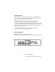
Table C-16: PCI/ISA slot pin assignments (Pins A and B) Pin 144 Signal Pin Signal A1 IOCHK B1 GND A2 SD7 B2 RST A3 SD6 B3 VCC A4 SD5 B4 IRQ9 A5 SD4 B5 NC A6 SD3 B6 DRQ2 A7 SD2 B7 -12 V A8 SD1 B8 OWS A9 SD0 B9 +12 V A10 IORDY B10 GND A11 AEN B11 SMW A12 SA19 B12 SMR A13 SA18 B13 IOW A14 SA17 B14 IOR A15 SA16 B15 DACK3 A16 SA15 B16 DRQ3 A17 SA14 B17 DACK1 A18 SA13 B18 DRQ1 A19 SA12 B19 REF A20 SA11 B20 SCLK A21 SA10 B21 I
Table C-17: PCI/ISA slot pin assignments (Pins C and D) Pin Signal Pin Signal C1 SBHE D1 MEM16 C2 LA23 D2 IO16 C3 LA22 D3 IRQ10 C4 LA21 D4 IRQ11 C5 LA20 D5 IRQ12 C6 LA19 D6 IRQ15 C7 LA18 D7 IRQ14 C8 LA17 D8 DACKO C9 MEMR D9 DRQ0 C10 MEMW D10 DACK5 C11 SD8 D11 DRQ5 C12 SD9 D12 DACK6 C13 SD10 D13 DRQ6 C14 SD11 D14 DACK7 C15 SD12 D15 DRQ7 C16 SD13 D16 V CC C17 SD14 D17 MASTER C18 SD15 D18 GND Appendix C Pin Assignments 145
Table C-18: PCI/ISA slot pin assignments (Pins E and F) 146 Pin Signal Pin Signal E1 GND F1 GND E2 GND F2 GND E3 INT 1 F3 INT3 E4 INT 2 F4 INT4 E5 VCC F5 VCC E6 --- F6 --- E7 VCC F7 VCC E8 RST F8 PCLK2 E9 GNT2 F9 (V) E10 REQ2 F10 GNT3 E11 GND F11 GND E12 PCLK1 F12 REQ3 E13 GND F13 AD31 E14 AD30 F14 AD29 E15 NC F15 NC E16 --- F16 --- E17 NC F17 NC E18 AD28 F18 AD27 E19 AD26 F19 AD25 E20 AD24 F20 CBE3 E21 AD22 F21 AD23 E
Table C-19: PCI/ISA slot pin assignments (Pins G and H) Pin Signal Pin Signal G1 --- H1 SERR G2 --- H2 AD15 G3 CBE1 H3 AD14 G4 PAR H4 AD12 G5 GND H5 GND G6 --- H6 KEY G7 GND H7 GND G8 AD13 H8 AD10 G9 AD11 H9 AD8 G10 AD9 H10 AD7 G11 CBEO H11 AD5 G12 AD6 H12 AD3 G13 AD4 H13 AD1 G14 AD2 H14 AD0 G15 --- H15 KEY G16 V CC H16 V CC G17 V CC H17 V CC G18 GND H18 GND G19 GND H19 GND Appendix C Pin Assignments 147
C.