
User`s manual


RS-100-RT User’s Manual
22
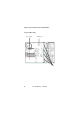
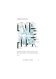
The description of jumpers on the motherboard
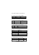
l CN24-Power Bottom / PCI64 33/66MHz
Jumper Function Remark
1-2 Close to Open
Power On >0.5 Sec
3-4 Closed PCI64 run 33MHz Normal PCI64 run 66MHz
l J10-Power On for Special Power supply
Jump er Function Remark
1-2 Closed Power bottom on / off
For 1U and 2U redundant
power supply
2-3 Closed Power supply switch on / off For 2U single power supply
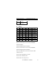
l J8-Load default or System reset function
Jumper Function Remark
1-2 Closed Load Default For LED board system-reset bottom (S2)
2-3 Closed System Reset For LED board system-reset bottom (S2)
l J6- LAN1 & LAN2 LED indicator
Function Jumper
On board 82559 LAN1 LED PIN 1-2 Closed
On board 82559 LAN2 LED PIN 3-4 Closed
On board 82559 LAN3 LED PIN 3-4 Closed
Add-on-card Gigabit
LAN1
LED
Gigabit Lan1 Active LED connect J6 pin2
Add-on-card Gigabit
LAN2
LED
Gigabit Lan2 Active LED connect J6 pin4
Addon-card Gigabit LAN3 LED
Gigabit Lan3 Active LED connect J6 pin6
l JP1-Alarm board device sensor setting .
Jumper Function Remark
PIN 1-2,3-4,5-6,7-8,9-10 Closed RS-100-RT One CPU Note1,3
PIN 3-4,5-6,7-8,9-10 Closed RS-100-RT Two CPU
Note1
PIN 1-2,5-6,7-8,9-10 Closed RS-100-RT One CPU Note2,3