
User manual


9 PDC-190S User Manual
Chapter 2 System Setup
PDC-190S is equipped with an on-screen menu for making various adjustments and
settings such as picture control, input setting, set setting change, etc. You can also
change the menu language display in the on-screen menu.
The OSD control switch is located on the front bezel. For detailed information please
refer to Appendix-A “OSD Selections”.
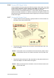
When you turn the PDC-190S around and look at its rear cover, you will find the
sunken I/O section is at the bottom of the PDC-190S, as shown in Fig. 2-2. (The I/O
section includes various I/O ports, including the DVI-I, Component Video, S-Video,
USB ports, and the line-in jack.
Figure 2.2 I/O Section of PDC-190S
Menu/Escape
Displays or sets the on-screen menu
Press to display the on-screen menu.
Press again to clean the menu and will save the value
of adjustment items.
Multi-display On/Off
Multiple display Enable/Display
Press to enable/disable multiple display.
Table 2.2: I/O Connectors of PDC-190S
No I/O Function
DC 12V IN connector (DIN 4
pins)
Connect the DC connect of the supplied AC
adapter.
Serial Remote RS-232C con-
nector (D-Sub 9)_
Connect to the RS-232C control connector on
external equipment connected to the monitor.
Composite IN connector
(BNC, left)
Composite Out connector
(BNC, right)
Input connector for composite signals.
Loop-through output of the composite IN con-
nector
HD/SD SDI IN connector
(BNC, top)
HD/SD SDI Out connector
(BNC, bottom)
Input connector for HD/SD SDI signals.
Loop-through output of the HD/SD SDI IN con-
nector
Y/C IN connector (4-pin mini
DIN, top)
Y/C Out connector (4-pin mini
DIN, bottom)
Input connector for Y/C signals.
Loop-through output of the Y/C IN connector