
User manual


PDC-190S User Manual 4
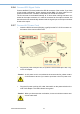
1.3 Connectors
Figure 1.1 PDC-190S connection port
The following connectors are situated on the rear of the PDC-190S (From left to
right):
1.3.1 DC 12V Power In
The connector is connected to the DC 12V Switching Power Supply.
1.3.2 Analog and Digital Port (DVI-I)
The DVI-I connector integrates the analog RGB and digital DVI in one port, that can
be selected via "source" OSD button to switch which signal you want to input into the
monitor. Use of the scan converter allows the monitor to detect VGA, SVGA, XGA
and SXGA signal input. The details of compatible timings are listed in Appendix B of
this manual.
Table 1.1: Description of the DVI-I Port
Pin No. Function Description
1 T.M.D.S. Data2-
2 T.M.D.S. Data2+
3 T.M.D.S. Data2/4 Shield
4 T.M.D.S. Data4-
5 T.M.D.S. Data4+
6 DDC Clock
7 DDC Data
8 Analog Vertical Sync
9 T.M.D.S. Data1-
10 T.M.D.S. Data1+
11 T.M.D.S. Data1/3 Shield
12 T.M.D.S. Data3-
13 T.M.D.S. Data3+
14 +5V Power
15 Ground (for +5 V)
16 Hot Plug detect