
User manual
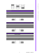

PCM-9590 User Manual 14
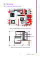
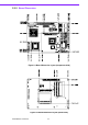
2.2.2 Connector Settings
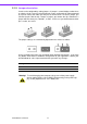
2.2.2.1 VGA/LCD/LVDS interface connections (CN2, CN18, CN23)
The board’s PCI VGA interface can drive conventional CRT displays and is capable
of driving a wide range of flat panel displays, including passive LCD and active LCD
displays. The board has connectors to support these displays: one for standard CRT
VGA monitors, or flat panel displays, and one for LVDS type LCD panels.
CRT display connector (CN18)
The CRT display connector is a BOX HEADER 8*2P 180D (M) 2.00 mm con-
nector used for conventional CRT displays.
LVDS LCD panel connector (CN2)
The board supports 2 channel 36 bit LVDS LCD panel display.
Users can connect to an 36 bit LVDS LCD on it.
LCD Backlight connector (CN23)
The LCD inverter is connected to CN23 via a 5-pin connector to provide +5V/
+12V power.
2.2.2.2 Ethernet configuration (CN1, CN3, CN8)
The board is equipped with 2 high performance PCI-E Ethernet interfaces which are
fully compliant with IEEE 802.3u 100Base-T & IEEE 802.3ab 1000Base-T. It is sup-
ported by all major network operating systems.
10/100/1000 Mbps connector (CN3, CN8)
10/100/1000 Mbps connections are made via the BOX HEADER 5*2P 2.0mm
connectors.
Gigabit LAN led connector (CN1)
The LAN LED indicator is for ethernet activity LED indicator.
2.2.2.3 SATA Connector (CN4, CN5)
PCM-9590 supports Serial ATA via two connectors (CN4, CN5). Data transfer rates
up to 300 MB/s, enabling very fast data and file transfer, and independent DMA ope
ration on two ports.
2.2.2.4 GPIO (General Purpose Input Output) (CN6,CN7)
The board supports 16-bit GPIO through GPIO connector.
The digital in and out-puts can be programmed as input data or output to devices,
with input or output defined (CN6,CN7).
2.2.2.5 USB connectors (CN9, CN11, CN14)
The board provides up to six USB (Universal Serial Bus) ports. This gives complete
Plug and Play, and hot attach/detach for up to 127 external devices. The USB inter-
faces comply with USB specification Rev. 2.0 which supports 480 Mbps transfer rate,
and are fuse protected.
5 x 2 pin header connectors, CN9, CN11, CN14. You will need an adapter cable if you
use a standard USB connector. The adapter cable has a 5 x 2-pin connector with pro-
tect function for plug in wrong direction on one end and a USB connector on the
other.
Pin Signal Pin Signal
1 +2.5 V_LAN1 2 GND
3 LAN1_LINKLED 4 LAN2_LINKLED
5 LAN1_ACTLED 6 LAN2_ACTLED
7 LAN1-LINK1000# 8 LAN2_LINK1000#