User Manual PCM-9590
Copyright This document is copyrighted, © 2008. All rights are reserved. The original manufacturer reserves the right to make improvements to the products described in this manual at any time without notice. No part of this manual may be reproduced, copied, translated or transmitted in any form or by any means without the prior written permission of the original manufacturer. Information provided in this manual is intended to be accurate and reliable.
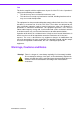
Product Warranty (2 years) Warranty Period ADVANTECH aims to meet the customer’s expectations for post-sales service and support; therefore, in addition to offering 2 years global warranty for ADVANTECH’s standard products, a global extended warranty service is also provided for customers upon request. ADVANTECH customers are entitled to a complete and prompt repair service beyond the standard 2 years of warranty.
FCC This device complies with the requirements in part 15 of the FCC rules: Operation is subject to the following two conditions: 1. This device may not cause harmful interference, and 2. This device must accept any interference received, including interference that may cause undesired operation This equipment has been tested and found to comply with the limits for a Class A digital device, pursuant to Part 15 of the FCC Rules.
Technical Support and Assistance For more information about this and other Advantech products, please visit our website at: http://www.advantech.com/ http://www.advantech.com/ePlatform/ For technical support and service, please visit our support website at: http://support.advantech.com.tw/support/ Additional Information and Assistance 1. 2. Visit the Advantech web site at http://www.advantech.com/ where you can find the latest product information.
Ordering Information Model Number Description PCM-9590FG-00A2E SKT w/ GigaLAN/ 8xUSB2.0/ PCI-E x 16/ Single LVDS PCM-9590FG-S2A2E Dual Core 1.2GHz 2M L2 w/GigaLAN/8xUSB2.0/ PCI-E x 16/ LVDS PCM-9590FG-S6A2E Dual Core 1.66GHz 2M L2 w/GigaLAN/8xUSB2.0/ PCI-E x 16/ LVDS Optional Accessories Model Number Description 1700006200 AT Power Cable 6*2P to 10*2P 100mm PCM-9590 PCM-10586-9590E Wiring kit for PCM-9590 Series MIO-3120-00A1E Mini PCI interface to Wireless 802.
Contents Chapter 1 General Introduction ...........................1 1.1 1.2 Introduction ............................................................................................... 2 Product Specifications............................................................................... 2 1.2.1 General ......................................................................................... 2 1.2.2 I/O .................................................................................................
3.2.12 Save & Exit Setup....................................................................... 35 3.2.13 Quit Without Saving .................................................................... 35 Chapter 4 S/W Installation ................................. 37 4.1 4.2 S/W Introduction ..................................................................................... 38 Driver Installation .................................................................................... 38 4.2.
Appendix B Optional Extras ..................................67 B.1 Optional Extras........................................................................................ 68 Table B.1: PCM-10586-9590E Cable kit for PCM-9590 ............ 68 Ordering Information ............................................................................... 68 B.
PCM-9590 User Manual x
Chapter 1 1 General Introduction This chapter gives background information on the PCM-9590.
1.1 Introduction The PCM-9590 is an EBX SBC (Single Board Computer) with Intel Core Duo CPU on board or socket type up to Core 2 Duo grade. The PCM-9590, in conjunction with Intel 945 GME and ICH7M chipsets, supports processors clocked up to 2.2 GHz, six USB 2.
Chipset: Intel 945GME chip integrated (Inter Gen 3.5 integrated graphic engine) Memory Size: 32-bit interface to address up to 32 MB of memory Resolution: CRT Display mode: pixel resolution up to QXGA (2048 x 1536) LCD Display mode: Dual channel LVDS panel supports up to UXGA panel resolution with frequency range from 25 MHz to 112 MHz LVDS: 2 Channel LVDS 1 (36-bit) LVDS2 (48-bit) optional by request Dual Ind.
1.3.1.3 Chipset (ICH7M) IDE Interface ICH7M Supports Single, independent IDE signal channel Supports up to two IDE devices with independent timings Ultra ATA/100/66/33 and PIO modes IDE Primary Connector: 40 pins 2.54 mm Box Header H.D. Codec ALC883 I/F Concurrent PCI Bus Controller SATA Connector ICH7M Supports Support for three AC’97 2.
Serial ports SMSC3114 (LPC Super I/O) supports. 4 full function serial ports. High Speed NS16C550A Compatible UARTs with Data rates to 1.5 Mbps Support IRQ Sharing among serial ports RS-485 Auto Direction Control Mode Connectors: 40 pins 2.0 mm 20 X 2 Box Header – COM1 (RS-232) – COM2 (RS-232/422/485 with auto-flow control) – COM3 ~ 4 (RS-232) Thermal sensor SMSC3114 (LPC Super I/O) supports Parallel port SMSC3114 (LPC Super I/O) supports One Parallel Port SPP/EPP (1.7,1.
1.3.2 Mechanical Spec. 1.3.2.1 Dimension (mm) 203 mm (L) * 146 mm (W) 1.3.2.2 Height on Top (mm) 29.3 mm (with Heatsink), 27 mm (with FAN cooler) 1.3.2.3 Height on Bottom (mm) 9.2 mm (memory socket) 1.3.2.4 Heatsink Dimension (mm) L50 mm * W50 mm * H24.7 mm (Heatsink) 1.3.2.5 Weight (g) with Heatsink 345 g (Heat sink) 1.3.3 Electrical Spec. 1.3.3.
CPU Type Status +5 V +12 V 512MB/533 BIOS Picture T7400 2.16GHz FSB=667 L2=4M CPU Type CPU Type CPU Type +12 V 1G/533/Kingston 1G*2/533/Transcend 1.07 A 1.22 A 1.99 A 1.96 A 0.9 A 1.99 A 1.02 A 2.01 A 0.96 A 0.81 A 1.13 A 0.81 A Win HCT11.2 1.03 A 2.09 A 1.34 A 2.08 A Intel TAT 100% 0.99 A 3.75 A 1.15 A 4.05 A +5 V +12 V +5 V +12 V Status +5 V +12 V 1G/533/Kingston 1G*2/533/Transcend 1.06 A 1.19 A 1.88 A 1.87 A DOS Idle 0.91 A 1.93 A 1.02 A 1.
1.3.4 Environmental Spec. 1.3.4.1 Operating temperature The Intel® Core Duo CPU® is specified for proper operation when the junction temperature is within the specified range of 0°C to 100°C. The Intel® 945GME chipset temperature runs at a maximum of 99°C. The Intel® ICH7M I/O Controller case temperature runs at a maximum of 99°C. The processor protects itself from catastrophic overheating by use of an internal thermal sensor at a temperature level of approximately 100°C.
Chapter 2 2 H/W Installation This chapter explains the setup procedures of the PCM-9590 hardware, including instructions on setting jumpers and connecting peripherals, switches, indicators and mechanical drawings. Be sure to read all safety precautions before you begin the installation procedure.
2.1 Jumpers 2.1.1 Jumper list J1: J2: J3: J4: LVDS1 panel power PC104+ VIO Selection COM2 function option Clear CMOS function J5: LVDS2 panel power J6: AT Power Solution 2.1.2 Jumper Settings Table 2.1: J1 J1 LVDS1 panel power PIN HEADER 3*1P 2.0 mm Setting Function 1-2 +5 V (Default) 2-3 +3.3 V Table 2.2: J2 J2 PC104+ VIO Selection PIN HEADER 3*1P 2.54 mm Setting Function 1-2 VIO = + 5 V (Default) 2-3 VIO = +3.3 V Table 2.3: J3 J3 COM2 function option PIN HEADER SMD 5*2P 180D(M) 2.
Chapter 2 H/W Installation Table 2.4: J4 J4 Clear CMOS function PIN HEADER 3*1P 2.0 mm Setting Function 1-2 Normal (Default) 2-3 Clear CMOS Table 2.5: J5 J5 LVDS2 panel power Setting Function 1-2 +5 V* 2-3 +3.3 V Table 2.6: J6 J6 AT Power Solution PIN HEADER 3*1P 2.
2.1.3 Jumper description Cards can be configured by setting jumpers. A jumper is a metal bridge used to close an electric circuit. It consists of two metal pins and a small metal clip (often protected by a plastic cover) that slides over the pins to connect them. To close a jumper, you connect the pins with the clip. To open a jumper, you remove the clip. Sometimes a jumper will have three pins, labeled 1, 2 and 3. In this case you would connect either pins 1 and 2, or 2 and 3.
Chapter 2 H/W Installation 2.2 Connectors 2.2.1 Connector list Table 2.
2.2.2 Connector Settings 2.2.2.1 VGA/LCD/LVDS interface connections (CN2, CN18, CN23) The board’s PCI VGA interface can drive conventional CRT displays and is capable of driving a wide range of flat panel displays, including passive LCD and active LCD displays. The board has connectors to support these displays: one for standard CRT VGA monitors, or flat panel displays, and one for LVDS type LCD panels. CRT display connector (CN18) The CRT display connector is a BOX HEADER 8*2P 180D (M) 2.
2.2.2.7 Floppy drive connector (CN12) You can attach floppy drive to the PCM-9590’s on-board controller. You can use any combination of 5.25” (360 KB and 1.2 MB) and/or 3.5” (720 KB, 1.44 MB, and 2.88 MB) drives. A 34-pin daisy-chain drive connector cable is required for a dual-drive system. On one end of the cable is a 34-pin flat-cable connector. On the other end are two sets of floppy disk drive connectors. Each set consists of a 34-pin flat-cable connector (usually used for 3.
2.2.2.10 Power connectors(CN21, CN24) Main power connector, +3.3 V, +5 V, +12 V PCM-9590 supports ATX and AT modes. Use ATX power cable (PN: 1700000265 ATX-20P(M)/12P(F) 10 CM) connect CN21,it’s change from 12pin to 20pin, provides 5 V and 12 V and other PS_ON signals. Optional AT power cable (PN: 1700006200 AT Power Cable 6*2P to 10*2P 10 cm ) connect CN21, it’s change from 12pin to 20pin, support AT power mode. This cable is optional base on additional request. 2.2.2.11 SMBUS (CN17) Supports SMBus 2.
2.3.1 Jumper and Connector Location PCIE1 CN32 J5 CN4 CN5 CN6 CN7 J2 CN1 CN2 J1 CN3 CN8 CN9 CN10 CN12 CN11 CN13 CN14 FAN1 CN15 CN18 J3 CN21 CN19 CN20 CN22 CN23 CN24 J6 J4 CN16 CN17 CN33 FAN2 CN28 CN27 CN26 Figure 2.1 Jumper and Connector Layout (Component Side) CN30 DIMM1 DIMM2 CN31 Figure 2.2 Jumper and Connector Layout (Solder Side) 17 PCM-9590 User Manual Chapter 2 H/W Installation 2.
2.3.2 Board Dimension Figure 2.3 Board Dimension Layout (Component Side) Figure 2.
Chapter 3 BIOS Operation 3
3.1 BIOS Introduction Advantech provides the full-featured AwardBIOS 6.0 which delivers superior performance, compatibility and functionality that manufactures of Industrial PC and Embedded boards demand; it’s many options and extensions let you customize your products to a wide range of applications and target markets. The modular, adaptable AwardBIOS 6.
Press to enter AwardBIOS CMOS Setup Utility, the Main Menu will appear on the screen. Use arrow keys to select among the items and press to accept or enter the sub-menu. Standard CMOS Features This setup page includes all the items in standard compatible BIOS. Advanced BIOS Features This setup page includes all the items of Award BIOS enhanced features. Advanced Chipset Features This setup page includes all the items of Chipset configuration features.
Load Optimized Defaults This setup page includes Load system optimized value, and the system would be in best performance configuration. Set Password Establish, change or disable password. Save & Exit Setup Save CMOS value settings to CMOS and exit BIOS setup. Exit Without Saving Abandon all CMOS value changes and exit BIOS setup. 3.2.2 Standard CMOS Features Date The date format is , , , . Week From Sun to Sat, determined and display by BIOS only Month From Jan to Dec.
None No floppy drive installed 360K, 5.25" 5.25 inch PC-type standard drive; 360K byte capacity 1.2M, 5.25" 5.25 inch AT-type high-density drive; 1.2M byte capacity 720K, 3.5" 3.5 inch double-sided drive; 720K byte capacity 1.44M, 3.5" 3.5 inch double-sided drive; 1.44M byte capacity 2.88M, 3.5" 3.5 inch double-sided drive; 2.88M byte capacity Halt on The item determines whether the computer will stop if an error is detected during power up.
3.2.3 Advanced BIOS Features Blank Boot [Disabled] (* Advantech feature enhancement) This item allows system only displays blank screen during BIOS Post stage. POST Beep [Enabled] (* Advantech feature enhancement) This item allows system send out Beep sound during BIOS Post stage. CPU Feature This item allows user to adjust CPU features, CPU ratio, VID and Thermal and special feature like XD flag. Hard Disk Boot Priority This item allows user to select boot sequence for system device HDD, SCSI, RAID.
Floppy Select boot device priority by Floppy. LS120 Select boot device priority by LS120. Hard Disk Select boot device priority by Hard Disk. CDROM Select boot device priority by CDROM. ZIP Select boot device priority by ZIP. USB-FDD Select boot device priority by USB-FDD. USB-ZIP Select boot device priority by USB-ZIP. USB-CDROM Select boot device priority by USB-CDROM. USB-HDD Select boot device priority by USB-HDD. LAN Select boot device priority by LAN.
Video BIOS Shadow [Enabled] Enabled copies Video BIOS to shadow RAM improves performance. Full Screen Logo Show [Enabled] Show full screen logo during post stage, and the Logo picture can be customization. Small Logo (EPA) Show [Enabled] Show EPA logo during system post stage. Summary Screen Show [Enabled] Show system status in Summary screen page. 3.2.
DRAM RAS# Precharge [Auto] This item enables users to set the DRAM RAS# precharge timing, system default is setting to “Auto” to reference the data from SPD ROM. System BIOS Cacheable [Enabled] This item allows the system BIOS to be cached to allow faster execution and better performance. Video BIOS Cacheable [Disabled] This item allows the video BIOS to be cached to allow faster execution and better performance.
OnChip IDE Device This item enables users to set the OnChip IDE device status, includes enable IDE devices and setting PIO and DMA access mode, and some of new chipset also support for SATA device (Serial-ATA). Onboard Device This item enables users to set the Onboard device status, includes enable USB, AC97, MC97 and LAN devices. Super IO Device This item enables users to set the Super IO device status, includes enable Floppy, COM, LPT, IR and control GPIO and Power fail status. 3.2.
Power Management [Min Saving] This item allows user to select system power saving mode. Min Saving Minimum power management. Suspend Mode=1 hr. Max Saving Maximum power management. Suspend Mode=1 min. User Define Allows user to set each mode individually. Suspend Mode= Disabled or 1 min ~1 hr. Video Off Method [DPMS] This item allows user to determine the manner is which the monitor is blanked.
USB KB Wake-Up From S3 [Enabled] This item allows user to enable using a USB keyboard, and allow a keystroke to wake up the system from power saving mode. Resume by Alarm [Disabled] This item allows user to enable and key in Date/time to power on system Disabled Disable this function. Enabled Enable alarm function to power on system. Data (of month) Alarm 1-31 Time (HH:MM:SS) Alarm (0-23) : (0-59) : 0-59) 3.2.
INT Pin 1~8 Assignment [Auto] The interrupt request (IRQ) line assigned to a device connected to the PCI interface on your system. 3.2.8 PC Health Status Note! This “PC Health Status” option controls the Thermal, FAN and Voltage status of the board. this page is developed by Chipset independent. Shutdown Temperature [Disabled] This item enables users to set the limitation of CPU temperature, the range is from 85°C through 100°C.
3.2.9 Frequency/voltage Control Note! This “Frequency/Voltage Control” option controls the CPU Host and PCI frequency, this page is developed by CPU and Chipset independent, some items will show up when you install a processor which supports this function. Auto Detect PCI Clk [Enabled] This item enables users to set the PCI Clk by system automatic detection or by manual. Spread Spectrum [Disabled] This item enables users to set the spread spectrum modulation.
Note! Chapter 3 BIOS Operation 3.2.10 Load Optimized Defaults Load Optimized Defaults loads the default system values directly from ROM. If the stored record created by the Setup program should ever become corrupted (and therefore unusable). These defaults will load automatically when you turn the PCM-9566 series system on. 3.2.
Note! To enable this feature, you should first go to the Advanced BIOS Features menu, choose the Security Option, and select either Setup or System, depending on which aspect you want password protected. Setup requires a password only to enter Setup. System requires the password either to enter Setup or to boot the system. A password may be at most 8 characters long. To Establish Password 1. Choose the Set Password option from the CMOS Setup Utility main menu and press . 2.
Note! Chapter 3 BIOS Operation 3.2.12 Save & Exit Setup Type “Y” will quit the BIOS Setup Utility and save user setup value to CMOS. Type “N” will return to BIOS Setup Utility. 3.2.13 Quit Without Saving Note! Type “Y” will quit the BIOS Setup Utility without saving to CMOS. Type “N” will return to BIOS Setup Utility.
PCM-9590 User Manual 36
Chapter 4 S/W Installation 4
4.1 S/W Introduction The mission of Advantech Embedded Software Services is to "Enhance quality of life with Advantech platforms and Microsoft Windows® embedded technology." We enable Windows® Embedded software products on Advantech platforms to more effectively support the embedded computing community. Customers are freed from the hassle of dealing with multiple vendors (Hardware suppliers, System integrators, Embedded OS distributor) for projects.
4.3.2.1 The GPIO API General Purpose Input/Output (GPIO) is a flexible parallel interface that allows a variety of custom connections, and supports digital I/O devices. 4.3.2.2 The I2C API I2C is a bi-directional two-wire bus that was developed by Philips for use in their televisions in the 1980s and nowadays is used in various types of embedded systems. The strict timing requirements defined in the I2C protocol has been taken care of by SUSI.
4.3.3.1 Windows XP In windows XP, you can install the library, drivers and demo programs onto the platform easily using the installation tool -- The SUSI Library Installer. After the installer has executed, the SUSI Library and related files for Windows XP can be found in the target installation directory. The files are listed in the following table. Table 4.1: Windows XP Directory Contents Susi.lib \Library Library for developing the applications on Windows XP. Susi.
4.3.4 SUSI Sample Programs 4.3.4.1 Sample Programs The sample programs demonstrate how to incorporate SUSI into your program. There are sample programs for two categories of operating system, i.e. Windows XP and Windows CE. The sample programs run in graphics mode in Windows XP and Windows CE. The sample programs are described in the subsections below. 4.3.4.2 Windows Graphics Mode There are sample programs of Windows in graphics mode for two categories of operating system, i.e. Windows CE and Windows XP.
4.3.4.4 GPIO When the application is executed, it will display GPIO information in the GPIO INFORMATION group box. It displays the number of input pins and output pins.
4.3.4.5 I2C When the application is executed, you can read or write a byte of data through I2C devices. All data must be read or written in hexadecimal system. Read a byte 43 PCM-9590 User Manual Chapter 4 S/W Installation pin functions. The GPIO pin assignments of the supported platforms are located in Appendix B. Test Read Single Input Pin – Click the radio button- Single-Pin. – Key in the pin number to read the value of the input pin. The Pin number starts from '0'.
– Key in the slave device address in Slave Address field. – Key in the register offset in Register Offset field. – Click the READ A BYTE button and then a byte of data from the device will be shown on the Result field. Write a byte – Key in the slave device address in Slave Address field. – Key in the register offset in Register Offset field. – Key in the desirous of data in Result field to write to the device. – Click the WRITE A BYTE button and then the data will be written to the device through I2C. 4.3.
45 PCM-9590 User Manual Chapter 4 S/W Installation – Click the WRITE SMBus DATA button and then the data will be written to the device through SMBus. Read a word – Click the radio button- Access a word. – Key in the slave device address in the Slave address field. – Key in the register offset in the Register Offset field. – Click the READ SMBus DATA button and then a word of data from the device will be shown on the Result field. Write a word – Click the radio button- Access a word.
4.3.4.7 VGA Control When the application is executed, it will display two blocks of VGA control functions. The application can turn on or turn off the screen shot freely, and it also can tune the brightness of the panels if your platform is being supported. You can test the functionalities of VGA control as follows: Screen on/off control – Click the radio button ON or push the key F11 to turn on the panel screen. – Click the radio button OFF or push the key F12 to turn off the panel screen.
Chapter 4 S/W Installation 4.3.4.8 Watchdog When the application is executed, it will display watchdog information in the WATCHDOG INFORMATION group box. It displays max timeout, min timeout, and timeout steps in milliseconds. For example, a 1~255 seconds watchdog will has 255000 max timeout, 1000 min timeout, and 1000 timeout steps. You can test the functionality of the watchdog as follows: Set the timeout value 3000 (3 sec.) in the SET TIMEOUT field and set the delay value 2000 (2 sec.
4.3.4.9 Hardware Monitor When the Monitor application is executed by clicking the button, hardware monitoring data values will be displayed. If certain data values are not supported by the platform, the correspondent data field will be grayed-out with a value of 0.
Chapter 5 Extension I/O Installation 5
5.1 PCI_E FORCE FORCE FORCE FORCE FORCE FORCE FORCE PCI-E PCB Align the slot on the PCIe PCB with the ribs of PCIe solt , then apply force evenly PCI-E SLOT 5.
Aim the pin connector to the foot print and apply force evenly. After applying force to the IPC connector, the footprint of the module/CPU board needs to be inserted correctly. After applying force to the connector, the footprint of the module/CPU board needs to be inserted correctly. 51 PCM-9590 User Manual Chapter 5 Extension I/O Installation 5.
PCM-9590 User Manual 52
Appendix A A Pin Assignments
A.1 Gigabit LAN led connector (CN1) Description: PIN HEADER 4*2P 180D (M) 2.0 mm DIP Pin Signal Pin Signal 1 +2.5 V_LAN1 2 GND 3 LAN1_LINK100# 4 LAN2_LINK100# 5 LAN1_ACTLED 6 LAN2_ACTLED 7 LAN1-LINK1000# 8 LAN2_LINK1000# A.2 LVDS1 connector (CN2)(CN32) Description: CONN. 40P 90D 1.25 mm SMD WO/Pb DF13-40DP-1.
Description: BOX HEADER 5*2P 180D (M) 2.0 mm DIP W/O Pb Pin Signal Pin Signal 1 NC 2 NC 3 MDI3P 4 MDI3N 5 MDI2P 6 MDI2N 7 MDI1P 8 MDI1N 9 MDI0P 10 MDI0N A.4 SATA connector 1 (CN4) Description: Serial ATA 7P 180D (M) DIP WO/Pb LD1807V-S51P Pin Signal 1 GND 2 TX+ 3 TX- 4 GND 5 RX- 6 RX+ 7 GND A.
A.6 DIO1 connector (CN6) Description: PIN HEADER 5*2 2.0 mm SMD Pin Signal Pin Signal 1 DIO0 2 DIO4 3 DIO1 4 DIO5 5 DIO2 6 DIO6 7 DIO3 8 DIO7 9 +5 V 10 GND A.7 DIO2 connector (CN7) Description: PIN HEADER 5*2 2.0 mm SMD Pin Signal Pin Signal 1 DIO8 2 DIO12 3 DIO9 4 DIO13 5 DIO10 6 DIO14 7 DIO11 8 DIO15 9 +5 V 10 GND A.8 LAN2 connector (CN8) Description: BOX HEADER 5*2P 180D (M) 2.
Description: PIN HEADER 5*2P 180D (M) 2.0 mm SMD Pin Signal Pin Signal +5 V 1 2 +5 V DAT- 3 4 DAT- DAT+ 5 6 DAT+ GND 7 8 GND GND 9 A.10 Printer port connector (CN10) Description: BOX HEADER 13*2P 180D (M) 2.
A.11 USB port 2/3 (CN11) Description: PIN HEADER 5*2P 180D (M) 2.0 mm SMD Pin Signal Pin Signal 1 +5 V 2 +5 V 3 DAT- 4 DAT- 5 DAT+ 6 DAT+ 7 GND 8 GND 9 GND A.12 Floppy connector (CN12) Description: BOX HEADER SMD 17*2P 180D (M) 2.
Description: BOX HEADER 20*2P 180D (M) 2.54 mm DIP NO.20P Pin Signal Pin Signal 1 RESET# 2 GND 3 D7 4 D8 5 D6 6 D9 7 D5 8 D10 9 D4 10 D11 11 D3 12 D12 13 D2 14 D13 15 D1 16 D14 17 D0 18 D15 19 GND 20 KEY 21 DREQ 22 GND 23 IOW# 24 GND 25 IOR# 26 GND 27 RDY 28 GND 29 DACK# 30 GND 31 IRQ14 32 NC 33 A1 34 DIAG# 35 A0 36 A2 37 CS0# 38 CS1# 39 DASP# 40 GND A.14 USB port 0/1 (CN14) Description: PIN HEADER 5*2P 180D (M) 2.
A.15 RS422 / RS485 connector (CN15) Description: PIN HEADER SMD 5*2P 180D (M) 2.0 mm Pin Signal Pin Signal 1 485-/TXD422- 2 485+/TXD422+ 3 RXD422- 4 RXD422+ A.16 SMBUS connector (CN17) Description: Wafer 2.54 mm 3P 180D (M) DIP W/LOCK22272031 Molex Pin Signal 1 GND 2 CLK 3 DAT 4 +3.3 V A.17 VGA connector (CN18) Description: BOX HEADER 8*2P 180D (M) 2.
Description: BOX HEADER 20*2P 180D (M) 2.
A.20 Power input connector (CN21) Description: Power CONN.6*2P 180D (M) DIP W/Fixed Lock Pin Signal Pin Signal 1 GND 7 GND 2 +5 V 8 GND 3 +5 V 9 +5 VSB 4 GND 10 PS_ON# 5 +5 V 11 GND 6 +5 V 12 +12 V A.21 TV-out connector (CN22) Description: WAFER BOX 2.0 mm 5P 180D MALE W/LOCK Pin Signal 1 Y_OUT 2 C_OUT 3 GND_TV 4 GND_TV 5 COMP_OUT A.22 LVDS1 backlight connector (CN23)(CN33) Description: WAFER BOX 2.
Description: Power Conn.2*2P 4.2 mm 180D (M) DIP 4200-WS-A1-2*2 Pin Signal 1 GND 2 GND 3 +12 V 4 +12 V A.24 Audio output connector (CN26) Description: PIN HEADER 12*2P 180D (M) 2.
A.26 KB/Mouse connector (CN28) Description: WAFER BOX 2.0 mm 6P 180D MALE W/LOCK Pin Signal 1 KBCLK 2 KBDAT 3 MSCLK 4 GND 5 +5 V_KB 6 MSDAT A.27 Extension SMBUS connector (CN29) Description: PIN HEADER 4*1P 180D (M) 2.
Pin Signal Pin Signal 1 +5 V_LVDS2 2 +5 V_LVDS2 3 GND 4 GND 5 +5 V_LVDS2 6 +5 V_LVDS2 7 LVDS2_D0- 8 LVDS1_D0- 9 LVDS2_D0+ 10 LVDS1_D0+ 11 GND 12 GND 13 LVDS2_D1- 14 LVDS1_D1- 15 LVDS2_D1+ 16 LVDS1_D1+ 17 GND 18 GND 19 LVDS2_D2- 20 LVDS1_D2- 21 LVDS2_D2+ 22 LVDS1_D2+ 23 GND 24 GND 25 LVDS2_CLK- 26 LVDS1_CLK- 27 LVDS2_CLK+ 28 LVDS1_CLK+ 29 GND 30 GND 31 LVDS2_DCLK 32 LVDS1_DDAT 33 GND 34 GND 35 LVDS0_D3- 36 LVDS1_D3- 37 LVDS0_D3+ 38
A.
Appendix B Optional Extras B
B.1 Optional Extras The PCM-9590 requires several cables for normal operation. You can make them yourself or purchase an optional cable kit assembly, which includes the following: Table B.1: PCM-10586-9590E Cable kit for PCM-9590 Part No. Cable Description PCM-9590 Cable Description Connector 1701400452 IDE Cable CN13 FLAT CABLE 40P GRAY FOR DMA-66 PIN20 I.P.
Appendix A Pin Assignments PCM-9590 User Manual 69
www.advantech.com Please verify specifications before quoting. This guide is intended for reference purposes only. All product specifications are subject to change without notice. No part of this publication may be reproduced in any form or by any means, electronic, photocopying, recording or otherwise, without prior written permission of the publisher. All brand and product names are trademarks or registered trademarks of their respective companies. © Advantech Co., Ltd.