
User manual


PCM-9342 User Manual 12
2.2.2.5 Parallel port connector (CN12)
Normally, the parallel port is used to connect the card to a printer. The board includes
a multi-mode (ECP/EPP/SPP) parallel port accessed via CN12 and a 26-pin flat-
cable connector. You will need an adapter cable if you use a traditional DB-25 con-
nector. The adapter cable has a 26-pin connector on one end, and a DB-25 connec-
tor on the other.
The parallel port is designated as LPT1, and can be disabled in the system BIOS
setup.
The parallel port interrupt channel is designated to be IRQ7.
You can select ECP/EPP DMA channel via BIOS setup.
2.2.2.6 TTL LCD panel connector (CN16)
The board supports 24bit TTL LCD panel displays.
Users can connect to an 24bit TTL LCD on it.
2.2.2.7 LVDS LCD panel connector (CN18)
The board supports 18bit LVDS LCD panel displays.
Users can connect to an 18bit LVDS LCD on it.
2.2.2.8 COM port connector (CN11, CN14, CN15, CN36)
The PCM-9342 provides 4 serial ports (COM1, COM3 & COM4: RS-232; COM2: RS-
232/422/485) in one DB-9 connector (CN36) for COM1 and one 7*2P pin header
(CN11) for COM2 and two 5*2P pin header(CN14, CN15) for COM3 & COM4. It pro-
vides connections for serial devices (a mouse, etc.) or a communication network.
You can find the pin assignments for the COM port connector in Appendix A.
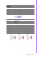
2.2.2.9 COM RS-232/422/485 setting (J2)
COM2 can be configured to operate in RS-232, RS-422, or RS-485 mode.
This is done via J2.
2.2.2.10 Ethernet configuration
The board is equipped with 1 high performance 32-bit PCI-bus Ethernet interface
which is fully compliant with IEEE 802.3 10/100Mbps. It is supported by all major net-
work operating systems.
2.2.2.11 100Base-T connector (CN19)
100Base-T connections are made via the on-board RJ-45 connector.
2.2.2.12 PC/104 Connector (CN21)
PCM-9342 supports full ISA compatible functions via PC/104 connector (CN21).
Socket2: 20 x 2 (F) 2.54 mm 51.86 mm x 5.01 mm x 11.45 mm p = 3.40 mm
Socket3: 32 x 2 (F) 2.54 mm 82.34 mm x 5.01 mm x 11.45 mm p = 3.40 mm
PC/104 negative voltage: One 3 x 1-pin wafer box (CN20) supports -5 V/-12 V power
input for ISA devices.
2.2.2.13 Power connectors
Main power connector, +5 V, +12 V (CN25).
J2 COM2 Setting
Setting Function
(1-2) RS232
(3-4) RS485
(5-6) RS422