User Manual PCM-9342
Copyright This document is copyrighted, © 2008. All rights are reserved. The original manufacturer reserves the right to make improvements to the products described in this manual at any time without notice. No part of this manual may be reproduced, copied, translated or transmitted in any form or by any means without the prior written permission of the original manufacturer. Information provided in this manual is intended to be accurate and reliable.
Product Warranty (2 years) Warranty Period ADVANTECH aims to meet the customer’s expectations for post-sales service and support; therefore, in addition to offering 2 years global warranty for ADVANTECH’s standard products, a global extended warranty service is also provided for customers upon request. ADVANTECH customers are entitled to a complete and prompt repair service beyond the standard 2 years of warranty.
Declaration of Conformity FCC This device complies with the requirements in part 15 of the FCC rules: Operation is subject to the following two conditions: 1. This device may not cause harmful interference, and 2. This device must accept any interference received, including interference that may cause undesired operation. This equipment has been tested and found to comply with the limits for a Class A digital device, pursuant to Part 15 of the FCC Rules.
Packing List Before installation, please ensure the following items have been shipped: Item Part Number 1 PCM-9342 SBC 1 Startup manual 1 Utility CD 1 mini jumper pack Cables Part Number Description 1700008894 1 SATA cable 1700060202 1 PS/2 Y cable 1700100250 2 COM3/COM4 cable 1700260250 1 x LPT port cable 1701140201 1 COM2 cable 1703100121 1 USB 2 port cable Optional accessories Model Number Description 1700001531 1 Floppy cable Ordering information Model Number Description PCM-9342F-64A1E E
PCM-9342 User Manual vi
Contents Chapter 1 General Introductin .............................1 1.1 1.2 Introduction ............................................................................................... 2 Product Feature ........................................................................................ 2 1.2.1 General ......................................................................................... 2 1.2.2 I/O ................................................................................................
A.1 A.2 A.3 A.4 A.5 A.6 A.7 A.8 A.9 A.10 A.11 A.12 A.13 A.14 A.15 A.16 A.17 A.18 A.19 A.20 A.21 VGA (CN5).............................................................................................. 32 Table A.1: CN5 .......................................................................... 32 SATA (CN6) ............................................................................................ 33 Table A.2: CN6 .......................................................................... 33 SATA (CN7) ...
Chapter 1 1 General Introductin This chapter gives background information on the PCM-9342.
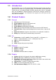
1.1 Introduction The PCM-9342 is an 3.5” SBC (Single Board Computer) with low power based on Advantech EVA-X4150 SoC (System on Chip). The PCM-9342, in conjunction with EVA-X4150 SoC and onboard 64MB SDRAM, supports two USB 2.0 compatible ports, one 10/100Base-T Ethernet interface, LVDS and TTL interface, and one PC/ 104 expansion connector. The PCM-9342 also supports two SATA (transfer from IDE) and four COM ports. 1.2 Product Feature 1.2.
Chapter 1 1.3 Chipset 1.3.1 Functional Specification 1.3.1.1 Processor Chipset Advantech Em’Core EVA-X4150 SoC 27 mm * 27 mm * 2.23 mm PBGA 456balls 1.3.1.
SMSC SCH 3114 supports (LPC Super I/O) PS/2 Keyboard and Mouse interface Connector: Mini-Din 6P at coastline Keyboard/Mouse Connectors SMSC SCH 3114 supports (LPC Super I/O) 8 I/O Pins 5 V tolerance I/Os GPIO Connectors: 10 pins 2.0 mm pin header Battery Backup 2 pin wafer box for external Battery on board 1.3.2 Mechanical Specification 1.3.2.1 Dimension(mm) L146.12 mm * W101.57 mm 1.3.2.2 Height on Top(mm) 13 mm (PS/2 Connector) 1.3.2.3 Height on Bottom(mm) 8.1 mm (CF Socket) 1.3.2.
Chapter 1 1.3.4 Environmental Specification 1.3.4.1 Operating Humidity 0% ~ 90% Relative Humidity, non-condensing 1.3.4.2 Operating temperature Operating temperature: 0 ~ 60° C (32 ~ 140° F) General Introductin 1.3.4.3 Storage Humidity Standard products (0~60° C) Relative Humidity: 95% @ 60° C 1.3.4.
PCM-9342 User Manual 6
Chapter 2 2 H/W Installation This chapter explains the setup procedures of the PCM-9342 hardware, including instructions on setting jumpers and connecting peripherals, switches, indicators and mechanical drawings. Be sure to read all safety precautions before you begin the installation procedure.
2.1 Jumpers 2.1.1 Jumper list J1 LCD Power J2 COM2 Setting J3 HDD & PWR LED Setting J4 CPU CLK Setting J5 CPU CLK Setting J6 CPU CLK Setting 2.1.2 Jumper Settings J1 LCD Power Part Number 1653003101 Footprint JH3X1V-2M Description PIN HEADER 3*1P 180D(M) 2.0mm DIP SQUARE W/O Pb Setting Function (1-2) +5 V (2-3)* +3.3 V *: Default J2 COM2 Setting Part Number 1653003260 Footprint JH3X2S-2M Description PIN HEADER 3*2P 180D(M) 2.
Part Number 1653000014 Footprint JH2X2S-2M Description PIN HEADER 2*2P 180D SMD MALE SQUARE 2.00mm Setting Function (1-2) (3-4)* IDE (Yellow) Power (Green) (1-3) (2-4) IDE(Green) Power (Yellow) H/W Installation HDD & PWR LED Setting *: Default J4-J6 CPU CLK Setting Part Number 1653003101 Footprint JH3X1V-2M Description PIN HEADER 3*1P 180D(M) 2.
2.1.3 Jumper description You may configure your card to match the needs of your application by setting jumpers. A jumper is a metal bridge used to close an electric circuit. It consists of two metal pins and a small metal clip (often protected by a plastic cover) that slides over the pins to connect them. To .close. a jumper, you connect the pins with the clip. To .open. a jumper, you remove the clip. Sometimes a jumper will have three pins, labeled 1, 2 and 3.
Chapter 2 2.2 Connectors 2.2.1 Connector list CN5 VGA CN6 SATA SATA CN9 Internal USB CN11 COM2 CN12 LPT CN14 COM3 CN15 COM4 CN16 24 bits TTL Panel CN17 Inverter Power Output CN18 18 bits LVDS Panel CN19 LAN CN20 ISA -5V & -12V Input CN21 PC104 CN25 AT Power Input CN32 GPIO CN33 Battery CN34 PS2 CN35 CF CN36 COM1 H/W Installation CN7 2.2.2 Connector Settings 2.2.2.
2.2.2.5 Parallel port connector (CN12) Normally, the parallel port is used to connect the card to a printer. The board includes a multi-mode (ECP/EPP/SPP) parallel port accessed via CN12 and a 26-pin flatcable connector. You will need an adapter cable if you use a traditional DB-25 connector. The adapter cable has a 26-pin connector on one end, and a DB-25 connector on the other. The parallel port is designated as LPT1, and can be disabled in the system BIOS setup.
2.2.2.14 GPIO (General Purpose Input Output) (CN32) The board supports 8-bit GPIO through GPIO connector. The 8 digital in and out-puts can be programmed to read or control devices, with input or output defined. The default setting is 4 bits input and 4 bits output. 2.2.2.16 Solid State Disk The board provides a CompactFlash card type I/II socket. CompactFlash (CN35) The CompactFlash card shares a secondary IDE channel which can be enabled/disabled via the BIOS settings.
2.3 Mechanical 2.3.1 Jumper and Connector Location J6 J5 CN17 CN7 CN6 J4 CN16 CN18 J1 CN20 CN25 CN12 CN21 CN14 CN33 CN15 J2 J3 CN32 CN9 CN11 CN19 CN34 CN36 LAN LED CN5 Reset Power & HDD LED Figure 2.1 Jumper and Connector Layout (Component Side) CN35 Figure 2.
Chapter 2 2.3.2 Board Dimension H/W Installation Figure 2.3 Board Dimension Layout (Component Side) Figure 2.
Figure 2.
Chapter 3 BIOS Operation Sections include: BIOS Introduction BIOS Setup 3
3.1 BIOS Introduction Advantech provide full-featured AwardBIOS 6.0 and delivers the superior performance, compatibility and functionality that manufactures of Industry PC and Embedded boards, it’s many options and extensions let you customize your products to a wide range of designs and target markets. The modular, adaptable AwardBIOS 6.
Press to enter AwardBIOS CMOS Setup Utility, the Main Menu will appear on the screen. Use arrow keys to select among the items and press to accept or enter the sub-menu. Chapter 3 3.2.1 Main Menu BIOS Operation Standard CMOS Features This setup page includes all the items in standard compatible BIOS. Advanced BIOS Features This setup page includes all the items of Award BIOS enhanced features.
3.2.2 Standard CMOS Features Date The date format is , , , . Week From Sun to Sat, determined and display by BIOS only Month From Jan to Dec. Day From 1 to 31 Year From 1999 through 2098 Time The times format in , base on the 24-hour time IDE Channel 0 Master/Slave IDE HDD Auto-Detection Press "Enter" for automatic device detection. IDE Channel 1 Master IDE HDD Auto-Detection Press "Enter" for automatic device detection. Drive A [1.44m, 3.5 in.
Chapter 3 3.2.3 Advanced BIOS Features 21 PCM-9342 User Manual BIOS Operation Hard Disk Boot Priority This item allows user to select boot sequence for system device HDD, SCSI, RAID. USB Boot Priority This item allows user to select USB Boot Device Priority. First / Second / Other Boot Drive Floppy Select boot device priority by Floppy. LS120 Select boot device priority by LS120. Hard Disk Select boot device priority by Hard Disk. CDROM Select boot device priority by CDROM.
Agent after boot [Disabled] This item allows user to set agent running after boot mode. Delay For HDD (Secs) [0] This item allows user to set delay for HDD(secs). USB Device Setting [Press Enter] (Show Only) This item allows users to set USB related features. 3.2.4 Advanced Chipset Features Note! This "Advanced Chipset Features" option controls the configuration of the board's chipset, this page is developed by Chipset independent, for control chipset register setting and fine tune system performance.
3.2.5 Integrated Peripherals Chapter 3 LPC 80H port decode [Disabled] This item allows users to set LPC of 80H port decode function. BIOS Operation Note! This "Integrated Peripherals" option controls the configuration of the board's chipset, includes IDE, ATA, this page is developed by Chipset independent. ADVSOC IDE Legacy mode [Enabled] This item enables ADVSOC IDE as legacy IDE controller or PCI IDE controller.
IDE HDD Block Mode [Enabled] This item allows enabled or disabled that IDE block data transfer mode. It will speed up HDD data transfer of efficiency. Bios default value suggest to “Enabled”. Onboard FDC Controller [Enabled] This item specifices onboard floppy disk drive controller. Onboard Serial Port 1 [3E8] This option is used to assign the I/O address and IRQ for the onboard serial port. Serial Port 1 Use IRQ [IRQ3] This option is used to assign the Serial Port 3 Use IRQ.
Chapter 3 Current SYS Temperature VCC 1.8 V 5V 12 V 3.2.7 Load Optimized Defaults BIOS Operation Note! Load Optimized Defaults loads the default system values directly from ROM. If the stored record created by the Setup program should ever become corrupted (and therefore unusable). These defaults will load automatically when you turn the PCM-9342 Series system on. 3.2.
Note! To enable this feature, you should first go to the Advanced BIOS Features menu, choose the Security Option, and select either Setup or System, depending on which aspect you want password protected. Setup requires a password only to enter Setup. System requires the password either to enter Setup or to boot the system. A password may be at most 8 characters long. To Establish Password 1. Choose the Set Password option from the CMOS Setup Utility main menu and press . 2.
Type "Y" will quit the BIOS Setup Utility and save user setup value to CMOS. Type "N" will return to BIOS Setup Utility. 3.2.10 Quit Without Saving Note! Type "Y" will quit the BIOS Setup Utility without saving to CMOS. Type "N" will return to BIOS Setup Utility. 27 PCM-9342 User Manual BIOS Operation Note! Chapter 3 3.2.
PCM-9342 User Manual 28
Chapter 4 PC/104 4
4.1 PC/104 Aim the pin connector to the footprint and apply force evenly. After apply force to the IPC connector. The footprint of the module / CPU board need to be inserted correctly. After apply force to the connector. The footprint of the modle / CPU board need to be inserted correctly.
Appendix A A Pin Assignments
A.1 VGA (CN5) Table A.1: CN5 CN5 VGA Part Number 1654515304 Footprint SUYIN_070207FR015S221CA Description D-SUB CONN.
Matching Cable: 1700006291 Table A.2: CN6 CN6 SATA Part Number 1654000172 Footprint SATA Description Serial ATA 7P 180D (M) DIP WO/Pb LD1807V-S51P Pin Pin Name 1 GND 2 TX+ 3 TX- 4 GND 5 RX- 6 RX+ 7 GND 33 PCM-9342 User Manual Appendix A Pin Assignments A.
A.3 SATA (CN7) Matching Cable: 1700006291 Table A.
Matching Cable: 1703100121 Table A.4: CN9 CN9 Internal USB Part Number 1653005260 Footprint HD_5x2P_79_N10 Description PIN HEADER 5*2P 180D (M) 2.0 mm SMD IDIOT-PROOF Pin Pin Name 1 +5 V 2 +5 V 3 A_D- 4 B_D- 5 A_D+ 6 B_D+ 7 GND 8 GND 9 GND 35 PCM-9342 User Manual Appendix A Pin Assignments A.
A.5 COM2 (CN11) Matching Cable: 1701140201 Table A.5: CN11 CN11 COM2 Part Number 1653207260 Footprint HD_7x2_79_BOX Description BOX HEADER SMD 7*2P 180D (M) 2.
Matching Cable: 1700260250 Table A.6: CN12 CN12 LPT Part Number 1653213260 Footprint BH13X2SV Description BOX HEADER 13*2P 180D (M) 2.0 mm SMD Pin Pin Name 1 STROBE# 2 AUTOFEED# 3 D0 4 ERROR# 5 D1 6 INIT# 7 D2 8 SLCT IN# 9 D3 10 GND 11 D4 12 GND 13 D5 14 GND 15 D6 16 GND 17 D7 18 GND 19 ACK# 20 GND 21 BUSY 22 GND 23 PE 24 GND 25 SLCT 26 NC 37 PCM-9342 User Manual Appendix A Pin Assignments A.
A.7 COM3 (CN14) Matching Cable: 1700100250 Table A.7: CN14 CN14 COM3 Part Number 1653205260 Footprint BH5X2SV Description BOX HEADER SMD 5*2 180D (M) 2.
Appendix A Pin Assignments A.8 COM4 (CN15) Matching Cable: 1700100250 Table A.8: CN15 CN15 COM4 Part Number 1653205260 Footprint BH5X2SV Description BOX HEADER SMD 5*2 180D (M) 2.
A.9 24 bits TTL Panel (CN16) Table A.9: CN16 CN16 24 bits TTL Panel Part Number 1653920200 Footprint SPH20X2 Description *CONN. 40P 90D 1.25 mm SMD WO/Pb DF13-40DP-1.25 V Pin Pin Name 1 +5 V 2 +5 V 3 GND 4 GND 5 +3.3 V 6 +3.
Appendix A Pin Assignments A.10 24 bits TTL Panel (CN16) Table A.10: CN16 CN16 24 bits TTL Panel Part Number 1653920200 Footprint SPH20X2 Description *CONN. 40P 90D 1.25 mm SMD WO/Pb DF13-40DP-1.
A.11 Inverter Power Output (CN17) Table A.11: CN17 CN17 Inverter Power Output Part Number 1655305020 Footprint WHL5V-2M Description WAFER BOX 2.
Table A.12: CN18 CN18 18 bits LVDS Panel Part Number 1653910261 Footprint SPH10X2 Description *CONN. SMD 10*2P 180D (M) DF13-20DP-1.25 V HRS Pin Pin Name 1 GND 2 GND 3 LVDS0_D0+ 4 NC 5 LVDS0_D0- 6 NC 7 LVDS0_D1+ 8 NC 9 LVDS0_D1- 10 NC 11 LVDS0_D2+ 12 NC 13 LVDS0_D2- 14 NC 15 LVDS0_CLK+ 16 NC 17 LVDS0_CLK- 18 NC 19 +5 V or +3.3 V 20 +5 V or +3.3 V 43 PCM-9342 User Manual Appendix A Pin Assignments A.
A.13 LAN (CN19) Table A.
Table A.14: CN20 CN20 ISA -5 V & -12 V Input Part Number 1653003101 Footprint JH3X1V-2M Description PIN HEADER 3*1P 180D (M) 2.0 mm DIP SQUARE W/O Pb Pin Pin Name 1 -12 V 2 -5 V 3 GND 45 PCM-9342 User Manual Appendix A Pin Assignments A.
A.15 PC104 (CN21) Table A.
Appendix A Pin Assignments Table A.
Table A.
Appendix A Pin Assignments Table A.
A.16 AT Power Input (CN25) Table A.19: CN25 CN25 AT Power Input Part Number 1655204030 Footprint PWR-4PV-508 Description HOUSING 5.
Table A.20: CN32 CN32 GPIO Part Number 1653005261 Footprint HD_5x2P_79_BOX Description PIN HEADER SMD 5*2P 180D (M) 2.0 mm Pin Pin Name 1 +5 V 2 GPIO4 3 GPIO0 4 GPIO5 5 GPIO1 6 GPIO6 7 GPIO2 8 GPIO7 9 GPIO3 10 GND 51 PCM-9342 User Manual Appendix A Pin Assignments A.
A.18 Battery (CN33) Table A.21: CN33 CN33 Battery Part Number 1655902032 Footprint WHL2V-125 Description WAFER 2P 180D (M) 1.
Table A.22: CN34 CN34 PS2 Part Number 1654606317 Footprint MINIDIN6 Description MINI DIN 6P 90D (F) DIP W/Shielded Purple w/o cd Pin Pin Name 1 KBDAT 2 MSDAT 3 GND 4 +5 V 5 KBCLK 6 MSCLK 53 PCM-9342 User Manual Appendix A Pin Assignments A.
A.
Appendix A Pin Assignments Table A.
A.21 COM1 (CN36) Table A.
Appendix B Watchdog Timer B
B.1 Watchdog Timer Sample Code ;The SCH3114 Runtime base I/O address is 800h ;Setting WatchDog time value location at offset 66h ;If set value "0", it is mean disable WatchDog function. Superio_GPIO_Port = 800h mov dx,Superio_GPIO_Port + 66h mov al,00h out dx,al .model small .486p .stack 256 .data SCH3114_IO EQU 800h .code org 100h .
59 PCM-9342 User Manual Appendix B Watchdog Timer ;==================================================== mov dx,SCH3114_IO + 68h mov al,01h out dx,al .
www.advantech.com Please verify specifications before quoting. This guide is intended for reference purposes only. All product specifications are subject to change without notice. No part of this publication may be reproduced in any form or by any means, electronic, photocopying, recording or otherwise, without prior written permission of the publisher. All brand and product names are trademarks or registered trademarks of their respective companies. © Advantech Co., Ltd.