
User`s manual
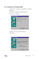

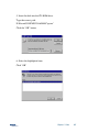
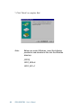
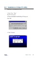


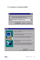
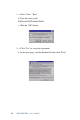
Table Of Contents
- Contents
- Chapter 1 General Information
- Chapter 2 Installation
- 2.1 Jumpers
- 2.2 Connectors
- 2.3 Locating jumpers
- 2.4 Locating connectors
- 2.5 Setting jumpers
- 2.6 CMOS clear (J3)
- 2.7 Installing system memory (DIMMs)
- 2.8 IDE, CDROM hard drive connector (CN16, CN17)
- 2.9 Solid State Disk
- 2.10 Floppy drive connector (CN19)
- 2.11 Parallel port connector (CN21, CN22)
- 2.12 Keyboard and PS/2 mouse connector (CN10)
- 2.13 Front panel connector (CN13)
- 2.14 Power connectors (CN24, CN8, CN26)
- 2.15 ATX power control connector (J4, CN5)
- 2.16 IR connector (CN27)
- 2.17 Audio interfaces (CN2, CN11)(PCM-9550F/9550FM only)
- 2.18 COM port connector (CN20)
- 2.19 VGA interface connections
- 2.20 VGA/TV-Out function select (J1)
- 2.21 Video In/Out interfaces (CN2) (PCM-9550FM only)
- 2.22 Ethernet configuration
- 2.23 Watchdog timer configuration
- 2.24 USB connectors (CN15)
- 2.25 Digital I/O (CN23, CN28: 8 Outputs, 8 Inputs)
- Chapter 3 Software Configuration
- Chapter 4 Award BIOS Setup
- 4.1 System test and initialization
- 4.2 AWARD BIOS setup
- 4.2.1 Entering setup
- 4.2.2 Standard CMOS setup
- 4.2.3 BIOS features setup
- 4.2.4 Chipset features setup
- 4.2.5 Power management setup
- 4.2.6 PnP/PCI configuration
- 4.2.7 Integrated peripherals
- 4.2.8 Load BIOS defaults
- 4.2.9 Change password
- 4.2.10 Auto detect hard disk
- 4.2.11 Save & exit setup
- 4.2.12 Exit without saving
- Chapter 5 PCI SVGA Setup
- Chapter 6 Video (PCM-9550FM)
- Chapter 7 Audio (PCM-9550F/9550FM)
- Chapter 8 PCI Bus Ethernet Interface
- Appendix A Programming the Watchdog Timer
- Appendix B Installing PC/104-Plus Modules
- Appendix C Pin Assignments
- C.1 CPU fan power connector (CN24)
- C.2 Ethernet 10/100Base-T connector (CN6)
- C.3 Audio connector (CN12)(PCM-9550F/9550FM only)
- C.4 CD audio input connector (CN11)(PCM-9550F/9550FM only)
- C.5 Main power connector (CN8)
- C.6 Keyboard and PS/2 mouse connector (CN10)
- C.7 Floppy disk drive connector (CN19)
- C.8 PC/104+ connectors (CN18)
- C.9 IDE HDD connector (CN16, 17)
- C.10 Parallel port connector (CN21, CN22)
- C.11 Front panel connector (J6)
- C.12 USB connector (CN15)
- C.13 LCD inverter backlight connector (CN7)
- C.14 IR connector (CN27)
- C.15 CRT display connector (CN1)
- C.16 Video in/out connector (CN2)
- C.17 24-bit LCD display connector (CN14)
- C.18 36-bit LCD display connector (CN9)
- C.19 Peripheral power connector (CN26)
- C.20 CompactFlash™ card connector (CN30)
- C.21 ATX power feature connector (CN5)
- C.22 Isolated 2 Digital Out (CN28)
- C.23 Digital I/O (CN23)
- C.24 COM port connector (CN20)
- Appendix D System Assignments
- Appendix E Optional Extras for the PCM-9550F/FM/L
- Appendix F Mechanical Drawings
- Table
- Table 2-1: Jumpers
- Table 2-2: Connector Assignments
- Table 2-3: CMOS clear (J3)
- Table 2-4: J8: DOC-2000 address setting
- Table 2-5: Audio power source setting
- Table 2-6: J9: COM2 RS-232/422/485 select
- Table 2-7: Serial port default settings
- Table 2-8: J10: COM1-4 RI settings
- Table 2-9: VGA/TV-Out function select (J1)
- Table 2-10: J2 TV out format select
- Table 2-11: LAN controller power select (J6)
- Table 2-12: Watchdog timer action (J11)
- Table 2-13: Digital output programming
- Table 2-14: Digital input programming
- Table 3-1: Connections to Sharp LM64183P & LM64P89
- Table 3-2: Connections to PLANAR EL
- Table 3-3: Connections to Toshiba LTM10DC042
- Table 3-4: Connections to Sharp LM64C142
- Table 3-5: Connections to Toshiba LTM12C2775A
- Table C-1: CPU fan power connector (CN24)
- Table C-2: Ethernet 10/100Base-T connector (CN6)
- Table C-3: Audio connector (CN12)
- Table C-4: Aux line-in connector (CN11)
- Table C-5: Main power connector (CN8)
- Table C-6: Keyboard and mouse connector (CN10)
- Table C-7: Floppy disk drive connector (CN19)
- Table C-8: PC/104+ connectors (CN18)
- Table C-9: PC/104+ Bus signal assignments (CN18)
- Table C-10: IDE HDD connector (CN16, CN17)
- Table C-11: Parallel port connector (CN21, CN22)
- Table C-12: Front panel connector (J6)
- Table C-13: USB connector (CN15)
- Table C-14: LCD inverter connector (CN7)
- Table C-15: IR connector (CN27)
- Table C-16: CRT display connector (CN1)
- Table C-17: Video in/out connector (CN2)
- Table C-18: 24-bit LCD display connector (CN14)
- Table C-19: 36-bit LCD display connector (CN9)
- Table C-20: Peripheral power connector (CN26)
- Table C-21: CompactFlash Card Connector (CN30)
- Table C-22: ATX power feature connector (CN5)
- Table C-23: Isolated Digital Out (CN28)
- Table C-24: Digital I/O (CN23)
- Table C-25: COM port connector (CN20)
- Table D-1: System I/O ports
- Table D-2: 1st MB memory map
- Table D-3: DMA channel assignments
- Table D-4: Interrupt assignments
- Figure
- Figure 1-1: PCM-9550 dimensions
- Figure 2-1: Locating jumpers
- Figure 2-2: Locating connectors (component side)
- Figure 2-3: Locating connectors (solder side)
- Figure 2-4: Wiring for ATX soft power switch function
- Figure 2-5: CN 23 Digital Input/Output
- Figure 2-6: Digital opto Isolated output block diagram
- Figure 2-7: CN28 Isolated Digital Output
- Figure 4-1: Setup program initial screen
- Figure 4-2: CMOS setup screen
- Figure 4-3: BIOS features setup
- Figure 4-4: Chipset features setup
- Figure 4-5: Power management setup
- Figure 4-6: PnP/PCI configuration
- Figure 4-7: Integrated peripherals
- Figure 4-8: Load BIOS defaults screen
- Figure B-1: PC/104+ module mounting diagram
- Figure B-2: PC/104+ module dimensions (mm) (±0.1)

86 PCM-9550F/FM/L User's Manual
7.1 Introduction
The PCM-9550F/FM on-board audio interface provides
high-quality stereo sound and FM music synthesis (ESFM) by
using the ES1373 audio controller from Creative Technology Ltd.
The audio interface can record, compress, and play back voice,
sound, and music with a built-in mixer control. The PCM-9550F/
FM's on-board audio interface also supports the Plug and Play
(PnP) standard and provides PnP configuration for audio, FM, and
MPU-104 logical devices. It is compatible with AC97 version 2.0,
voice, and music functions. The ESFM synthesizer is register
compatible with the OPL3 and has extended capabilities.
7.2 Installation of audio driver
Before installing the audio driver, please take note of the proce-
dures detailed below. You must know which operating system you
are using in your PCM-9550F/FM, and then refer to the corre-
sponding installation flow chart. Just follow the steps in the flow
chart. You can quickly and successfully complete the installation,
even though you are not familiar with instructions for Windows.
Note: The CD-ROM drive is designated as "D" through-
out this chapter.
Note: The PCM-9550F Audio driver is the same as
PCM-9574's. Users can reference it on the CD.
Note: 1. In step 1, for Windows 98, the path is:
'D:/Biscuit/9550F(9574)/audio/Win98/setup.exe.
2. In step 1 for Windows 2000, the path is:
D:/Biscuit/9550F(9574)/audio/win2k/setup.exe.
3. In step 1, for Windows NT, the path is:
D:/Biscuit/9550F(9574)/audio/winnt/setup.exe.