
User`s manual
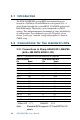
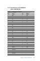
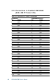
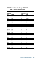
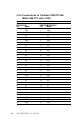
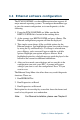

Table Of Contents
- Contents
- Chapter 1 General Information
- Chapter 2 Installation
- 2.1 Jumpers
- 2.2 Connectors
- 2.3 Locating jumpers
- 2.4 Locating connectors
- 2.5 Setting jumpers
- 2.6 CMOS clear (J3)
- 2.7 Installing system memory (DIMMs)
- 2.8 IDE, CDROM hard drive connector (CN16, CN17)
- 2.9 Solid State Disk
- 2.10 Floppy drive connector (CN19)
- 2.11 Parallel port connector (CN21, CN22)
- 2.12 Keyboard and PS/2 mouse connector (CN10)
- 2.13 Front panel connector (CN13)
- 2.14 Power connectors (CN24, CN8, CN26)
- 2.15 ATX power control connector (J4, CN5)
- 2.16 IR connector (CN27)
- 2.17 Audio interfaces (CN2, CN11)(PCM-9550F/9550FM only)
- 2.18 COM port connector (CN20)
- 2.19 VGA interface connections
- 2.20 VGA/TV-Out function select (J1)
- 2.21 Video In/Out interfaces (CN2) (PCM-9550FM only)
- 2.22 Ethernet configuration
- 2.23 Watchdog timer configuration
- 2.24 USB connectors (CN15)
- 2.25 Digital I/O (CN23, CN28: 8 Outputs, 8 Inputs)
- Chapter 3 Software Configuration
- Chapter 4 Award BIOS Setup
- 4.1 System test and initialization
- 4.2 AWARD BIOS setup
- 4.2.1 Entering setup
- 4.2.2 Standard CMOS setup
- 4.2.3 BIOS features setup
- 4.2.4 Chipset features setup
- 4.2.5 Power management setup
- 4.2.6 PnP/PCI configuration
- 4.2.7 Integrated peripherals
- 4.2.8 Load BIOS defaults
- 4.2.9 Change password
- 4.2.10 Auto detect hard disk
- 4.2.11 Save & exit setup
- 4.2.12 Exit without saving
- Chapter 5 PCI SVGA Setup
- Chapter 6 Video (PCM-9550FM)
- Chapter 7 Audio (PCM-9550F/9550FM)
- Chapter 8 PCI Bus Ethernet Interface
- Appendix A Programming the Watchdog Timer
- Appendix B Installing PC/104-Plus Modules
- Appendix C Pin Assignments
- C.1 CPU fan power connector (CN24)
- C.2 Ethernet 10/100Base-T connector (CN6)
- C.3 Audio connector (CN12)(PCM-9550F/9550FM only)
- C.4 CD audio input connector (CN11)(PCM-9550F/9550FM only)
- C.5 Main power connector (CN8)
- C.6 Keyboard and PS/2 mouse connector (CN10)
- C.7 Floppy disk drive connector (CN19)
- C.8 PC/104+ connectors (CN18)
- C.9 IDE HDD connector (CN16, 17)
- C.10 Parallel port connector (CN21, CN22)
- C.11 Front panel connector (J6)
- C.12 USB connector (CN15)
- C.13 LCD inverter backlight connector (CN7)
- C.14 IR connector (CN27)
- C.15 CRT display connector (CN1)
- C.16 Video in/out connector (CN2)
- C.17 24-bit LCD display connector (CN14)
- C.18 36-bit LCD display connector (CN9)
- C.19 Peripheral power connector (CN26)
- C.20 CompactFlash™ card connector (CN30)
- C.21 ATX power feature connector (CN5)
- C.22 Isolated 2 Digital Out (CN28)
- C.23 Digital I/O (CN23)
- C.24 COM port connector (CN20)
- Appendix D System Assignments
- Appendix E Optional Extras for the PCM-9550F/FM/L
- Appendix F Mechanical Drawings
- Table
- Table 2-1: Jumpers
- Table 2-2: Connector Assignments
- Table 2-3: CMOS clear (J3)
- Table 2-4: J8: DOC-2000 address setting
- Table 2-5: Audio power source setting
- Table 2-6: J9: COM2 RS-232/422/485 select
- Table 2-7: Serial port default settings
- Table 2-8: J10: COM1-4 RI settings
- Table 2-9: VGA/TV-Out function select (J1)
- Table 2-10: J2 TV out format select
- Table 2-11: LAN controller power select (J6)
- Table 2-12: Watchdog timer action (J11)
- Table 2-13: Digital output programming
- Table 2-14: Digital input programming
- Table 3-1: Connections to Sharp LM64183P & LM64P89
- Table 3-2: Connections to PLANAR EL
- Table 3-3: Connections to Toshiba LTM10DC042
- Table 3-4: Connections to Sharp LM64C142
- Table 3-5: Connections to Toshiba LTM12C2775A
- Table C-1: CPU fan power connector (CN24)
- Table C-2: Ethernet 10/100Base-T connector (CN6)
- Table C-3: Audio connector (CN12)
- Table C-4: Aux line-in connector (CN11)
- Table C-5: Main power connector (CN8)
- Table C-6: Keyboard and mouse connector (CN10)
- Table C-7: Floppy disk drive connector (CN19)
- Table C-8: PC/104+ connectors (CN18)
- Table C-9: PC/104+ Bus signal assignments (CN18)
- Table C-10: IDE HDD connector (CN16, CN17)
- Table C-11: Parallel port connector (CN21, CN22)
- Table C-12: Front panel connector (J6)
- Table C-13: USB connector (CN15)
- Table C-14: LCD inverter connector (CN7)
- Table C-15: IR connector (CN27)
- Table C-16: CRT display connector (CN1)
- Table C-17: Video in/out connector (CN2)
- Table C-18: 24-bit LCD display connector (CN14)
- Table C-19: 36-bit LCD display connector (CN9)
- Table C-20: Peripheral power connector (CN26)
- Table C-21: CompactFlash Card Connector (CN30)
- Table C-22: ATX power feature connector (CN5)
- Table C-23: Isolated Digital Out (CN28)
- Table C-24: Digital I/O (CN23)
- Table C-25: COM port connector (CN20)
- Table D-1: System I/O ports
- Table D-2: 1st MB memory map
- Table D-3: DMA channel assignments
- Table D-4: Interrupt assignments
- Figure
- Figure 1-1: PCM-9550 dimensions
- Figure 2-1: Locating jumpers
- Figure 2-2: Locating connectors (component side)
- Figure 2-3: Locating connectors (solder side)
- Figure 2-4: Wiring for ATX soft power switch function
- Figure 2-5: CN 23 Digital Input/Output
- Figure 2-6: Digital opto Isolated output block diagram
- Figure 2-7: CN28 Isolated Digital Output
- Figure 4-1: Setup program initial screen
- Figure 4-2: CMOS setup screen
- Figure 4-3: BIOS features setup
- Figure 4-4: Chipset features setup
- Figure 4-5: Power management setup
- Figure 4-6: PnP/PCI configuration
- Figure 4-7: Integrated peripherals
- Figure 4-8: Load BIOS defaults screen
- Figure B-1: PC/104+ module mounting diagram
- Figure B-2: PC/104+ module dimensions (mm) (±0.1)

48 PCM-9550F/FM/L User's Manual
4.1 System test and initialization
These routines test and initialize board hardware. If the routines
encounter an error during the tests, you will either hear a few short
beeps or see an error message on the screen. There are two kinds
of errors: fatal and non-fatal. With non-fatal errors, the system can
usually continue the boot sequence . Non-fatal error messages
usually appear on the screen along with the following instructions:
press <F1> to RESUME
Write down the message and press the F1 key to continue the boot
sequence.
4.1.1 System configuration verification
These routines check the current system configuration against the
values stored in the board’s CMOS memory. If they do not match,
the program outputs an error message. You will then need to run
the BIOS setup program to set the configuration information in
memory.
There are three situations in which you will need to change the
CMOS settings:
1. You are starting your system for the first time
2. You have changed the hardware attached to your system
3. The CMOS memory has lost power and the configuration
information has been erased.
The PCM-9550F/FM/L’s CMOS memory has an integral lithium
battery backup. The battery backup should last ten years in normal
service. When it finally runs down, you will need to replace the
complete unit.