
User`s manual


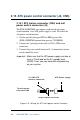

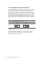
Table Of Contents
- Contents
- Chapter 1 General Information
- Chapter 2 Installation
- 2.1 Jumpers
- 2.2 Connectors
- 2.3 Locating jumpers
- 2.4 Locating connectors
- 2.5 Setting jumpers
- 2.6 CMOS clear (J3)
- 2.7 Installing system memory (DIMMs)
- 2.8 IDE, CDROM hard drive connector (CN16, CN17)
- 2.9 Solid State Disk
- 2.10 Floppy drive connector (CN19)
- 2.11 Parallel port connector (CN21, CN22)
- 2.12 Keyboard and PS/2 mouse connector (CN10)
- 2.13 Front panel connector (CN13)
- 2.14 Power connectors (CN24, CN8, CN26)
- 2.15 ATX power control connector (J4, CN5)
- 2.16 IR connector (CN27)
- 2.17 Audio interfaces (CN2, CN11)(PCM-9550F/9550FM only)
- 2.18 COM port connector (CN20)
- 2.19 VGA interface connections
- 2.20 VGA/TV-Out function select (J1)
- 2.21 Video In/Out interfaces (CN2) (PCM-9550FM only)
- 2.22 Ethernet configuration
- 2.23 Watchdog timer configuration
- 2.24 USB connectors (CN15)
- 2.25 Digital I/O (CN23, CN28: 8 Outputs, 8 Inputs)
- Chapter 3 Software Configuration
- Chapter 4 Award BIOS Setup
- 4.1 System test and initialization
- 4.2 AWARD BIOS setup
- 4.2.1 Entering setup
- 4.2.2 Standard CMOS setup
- 4.2.3 BIOS features setup
- 4.2.4 Chipset features setup
- 4.2.5 Power management setup
- 4.2.6 PnP/PCI configuration
- 4.2.7 Integrated peripherals
- 4.2.8 Load BIOS defaults
- 4.2.9 Change password
- 4.2.10 Auto detect hard disk
- 4.2.11 Save & exit setup
- 4.2.12 Exit without saving
- Chapter 5 PCI SVGA Setup
- Chapter 6 Video (PCM-9550FM)
- Chapter 7 Audio (PCM-9550F/9550FM)
- Chapter 8 PCI Bus Ethernet Interface
- Appendix A Programming the Watchdog Timer
- Appendix B Installing PC/104-Plus Modules
- Appendix C Pin Assignments
- C.1 CPU fan power connector (CN24)
- C.2 Ethernet 10/100Base-T connector (CN6)
- C.3 Audio connector (CN12)(PCM-9550F/9550FM only)
- C.4 CD audio input connector (CN11)(PCM-9550F/9550FM only)
- C.5 Main power connector (CN8)
- C.6 Keyboard and PS/2 mouse connector (CN10)
- C.7 Floppy disk drive connector (CN19)
- C.8 PC/104+ connectors (CN18)
- C.9 IDE HDD connector (CN16, 17)
- C.10 Parallel port connector (CN21, CN22)
- C.11 Front panel connector (J6)
- C.12 USB connector (CN15)
- C.13 LCD inverter backlight connector (CN7)
- C.14 IR connector (CN27)
- C.15 CRT display connector (CN1)
- C.16 Video in/out connector (CN2)
- C.17 24-bit LCD display connector (CN14)
- C.18 36-bit LCD display connector (CN9)
- C.19 Peripheral power connector (CN26)
- C.20 CompactFlash™ card connector (CN30)
- C.21 ATX power feature connector (CN5)
- C.22 Isolated 2 Digital Out (CN28)
- C.23 Digital I/O (CN23)
- C.24 COM port connector (CN20)
- Appendix D System Assignments
- Appendix E Optional Extras for the PCM-9550F/FM/L
- Appendix F Mechanical Drawings
- Table
- Table 2-1: Jumpers
- Table 2-2: Connector Assignments
- Table 2-3: CMOS clear (J3)
- Table 2-4: J8: DOC-2000 address setting
- Table 2-5: Audio power source setting
- Table 2-6: J9: COM2 RS-232/422/485 select
- Table 2-7: Serial port default settings
- Table 2-8: J10: COM1-4 RI settings
- Table 2-9: VGA/TV-Out function select (J1)
- Table 2-10: J2 TV out format select
- Table 2-11: LAN controller power select (J6)
- Table 2-12: Watchdog timer action (J11)
- Table 2-13: Digital output programming
- Table 2-14: Digital input programming
- Table 3-1: Connections to Sharp LM64183P & LM64P89
- Table 3-2: Connections to PLANAR EL
- Table 3-3: Connections to Toshiba LTM10DC042
- Table 3-4: Connections to Sharp LM64C142
- Table 3-5: Connections to Toshiba LTM12C2775A
- Table C-1: CPU fan power connector (CN24)
- Table C-2: Ethernet 10/100Base-T connector (CN6)
- Table C-3: Audio connector (CN12)
- Table C-4: Aux line-in connector (CN11)
- Table C-5: Main power connector (CN8)
- Table C-6: Keyboard and mouse connector (CN10)
- Table C-7: Floppy disk drive connector (CN19)
- Table C-8: PC/104+ connectors (CN18)
- Table C-9: PC/104+ Bus signal assignments (CN18)
- Table C-10: IDE HDD connector (CN16, CN17)
- Table C-11: Parallel port connector (CN21, CN22)
- Table C-12: Front panel connector (J6)
- Table C-13: USB connector (CN15)
- Table C-14: LCD inverter connector (CN7)
- Table C-15: IR connector (CN27)
- Table C-16: CRT display connector (CN1)
- Table C-17: Video in/out connector (CN2)
- Table C-18: 24-bit LCD display connector (CN14)
- Table C-19: 36-bit LCD display connector (CN9)
- Table C-20: Peripheral power connector (CN26)
- Table C-21: CompactFlash Card Connector (CN30)
- Table C-22: ATX power feature connector (CN5)
- Table C-23: Isolated Digital Out (CN28)
- Table C-24: Digital I/O (CN23)
- Table C-25: COM port connector (CN20)
- Table D-1: System I/O ports
- Table D-2: 1st MB memory map
- Table D-3: DMA channel assignments
- Table D-4: Interrupt assignments
- Figure
- Figure 1-1: PCM-9550 dimensions
- Figure 2-1: Locating jumpers
- Figure 2-2: Locating connectors (component side)
- Figure 2-3: Locating connectors (solder side)
- Figure 2-4: Wiring for ATX soft power switch function
- Figure 2-5: CN 23 Digital Input/Output
- Figure 2-6: Digital opto Isolated output block diagram
- Figure 2-7: CN28 Isolated Digital Output
- Figure 4-1: Setup program initial screen
- Figure 4-2: CMOS setup screen
- Figure 4-3: BIOS features setup
- Figure 4-4: Chipset features setup
- Figure 4-5: Power management setup
- Figure 4-6: PnP/PCI configuration
- Figure 4-7: Integrated peripherals
- Figure 4-8: Load BIOS defaults screen
- Figure B-1: PC/104+ module mounting diagram
- Figure B-2: PC/104+ module dimensions (mm) (±0.1)

Chapter 2 Installation 25
2.16 IR connector (CN27)
This connector supports the optional wireless infrared
transmitting and receiving module. This module mounts on the
system case. You must configure the setting through BIOS setup.
2.17 Audio interfaces (CN2, CN11)
(PCM-9550F/9550FM only)
The PCM-9550F/FM is equipped with a high-quality audio
interface, which provides 16-bit CD-quality recording and
playback as well as OPL3 compatible FM music. It is supported
by all major operating systems.
2.17.1 Audio connector (CN12)
The PCM-9550F/FM provides all major audio signals on a 16-pin
flat-cable connector, CN4. These audio signals include
Microphone in (mono), Line in (stereo), Line out (stereo), and
Speaker out (stereo). If you use traditional telephone jack
connectors for these audio signals, you will need an adapter cable.
2.17.2 CD audio input connector (CN11)
Any CD-ROM drive can provide analog audio signal output when
used as a music CD player. The CN11 on PCM-9550F/FM is a
connector to input CD audio signals into the audio controller. The
audio cable of your CD-ROM drive will be used to connect to
CN11.