
User`s manual


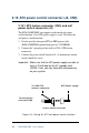

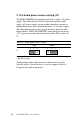
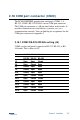
Table Of Contents
- Contents
- Chapter 1 General Information
- Chapter 2 Installation
- 2.1 Jumpers
- 2.2 Connectors
- 2.3 Locating jumpers
- 2.4 Locating connectors
- 2.5 Setting jumpers
- 2.6 CMOS clear (J3)
- 2.7 Installing system memory (DIMMs)
- 2.8 IDE, CDROM hard drive connector (CN16, CN17)
- 2.9 Solid State Disk
- 2.10 Floppy drive connector (CN19)
- 2.11 Parallel port connector (CN21, CN22)
- 2.12 Keyboard and PS/2 mouse connector (CN10)
- 2.13 Front panel connector (CN13)
- 2.14 Power connectors (CN24, CN8, CN26)
- 2.15 ATX power control connector (J4, CN5)
- 2.16 IR connector (CN27)
- 2.17 Audio interfaces (CN2, CN11)(PCM-9550F/9550FM only)
- 2.18 COM port connector (CN20)
- 2.19 VGA interface connections
- 2.20 VGA/TV-Out function select (J1)
- 2.21 Video In/Out interfaces (CN2) (PCM-9550FM only)
- 2.22 Ethernet configuration
- 2.23 Watchdog timer configuration
- 2.24 USB connectors (CN15)
- 2.25 Digital I/O (CN23, CN28: 8 Outputs, 8 Inputs)
- Chapter 3 Software Configuration
- Chapter 4 Award BIOS Setup
- 4.1 System test and initialization
- 4.2 AWARD BIOS setup
- 4.2.1 Entering setup
- 4.2.2 Standard CMOS setup
- 4.2.3 BIOS features setup
- 4.2.4 Chipset features setup
- 4.2.5 Power management setup
- 4.2.6 PnP/PCI configuration
- 4.2.7 Integrated peripherals
- 4.2.8 Load BIOS defaults
- 4.2.9 Change password
- 4.2.10 Auto detect hard disk
- 4.2.11 Save & exit setup
- 4.2.12 Exit without saving
- Chapter 5 PCI SVGA Setup
- Chapter 6 Video (PCM-9550FM)
- Chapter 7 Audio (PCM-9550F/9550FM)
- Chapter 8 PCI Bus Ethernet Interface
- Appendix A Programming the Watchdog Timer
- Appendix B Installing PC/104-Plus Modules
- Appendix C Pin Assignments
- C.1 CPU fan power connector (CN24)
- C.2 Ethernet 10/100Base-T connector (CN6)
- C.3 Audio connector (CN12)(PCM-9550F/9550FM only)
- C.4 CD audio input connector (CN11)(PCM-9550F/9550FM only)
- C.5 Main power connector (CN8)
- C.6 Keyboard and PS/2 mouse connector (CN10)
- C.7 Floppy disk drive connector (CN19)
- C.8 PC/104+ connectors (CN18)
- C.9 IDE HDD connector (CN16, 17)
- C.10 Parallel port connector (CN21, CN22)
- C.11 Front panel connector (J6)
- C.12 USB connector (CN15)
- C.13 LCD inverter backlight connector (CN7)
- C.14 IR connector (CN27)
- C.15 CRT display connector (CN1)
- C.16 Video in/out connector (CN2)
- C.17 24-bit LCD display connector (CN14)
- C.18 36-bit LCD display connector (CN9)
- C.19 Peripheral power connector (CN26)
- C.20 CompactFlash™ card connector (CN30)
- C.21 ATX power feature connector (CN5)
- C.22 Isolated 2 Digital Out (CN28)
- C.23 Digital I/O (CN23)
- C.24 COM port connector (CN20)
- Appendix D System Assignments
- Appendix E Optional Extras for the PCM-9550F/FM/L
- Appendix F Mechanical Drawings
- Table
- Table 2-1: Jumpers
- Table 2-2: Connector Assignments
- Table 2-3: CMOS clear (J3)
- Table 2-4: J8: DOC-2000 address setting
- Table 2-5: Audio power source setting
- Table 2-6: J9: COM2 RS-232/422/485 select
- Table 2-7: Serial port default settings
- Table 2-8: J10: COM1-4 RI settings
- Table 2-9: VGA/TV-Out function select (J1)
- Table 2-10: J2 TV out format select
- Table 2-11: LAN controller power select (J6)
- Table 2-12: Watchdog timer action (J11)
- Table 2-13: Digital output programming
- Table 2-14: Digital input programming
- Table 3-1: Connections to Sharp LM64183P & LM64P89
- Table 3-2: Connections to PLANAR EL
- Table 3-3: Connections to Toshiba LTM10DC042
- Table 3-4: Connections to Sharp LM64C142
- Table 3-5: Connections to Toshiba LTM12C2775A
- Table C-1: CPU fan power connector (CN24)
- Table C-2: Ethernet 10/100Base-T connector (CN6)
- Table C-3: Audio connector (CN12)
- Table C-4: Aux line-in connector (CN11)
- Table C-5: Main power connector (CN8)
- Table C-6: Keyboard and mouse connector (CN10)
- Table C-7: Floppy disk drive connector (CN19)
- Table C-8: PC/104+ connectors (CN18)
- Table C-9: PC/104+ Bus signal assignments (CN18)
- Table C-10: IDE HDD connector (CN16, CN17)
- Table C-11: Parallel port connector (CN21, CN22)
- Table C-12: Front panel connector (J6)
- Table C-13: USB connector (CN15)
- Table C-14: LCD inverter connector (CN7)
- Table C-15: IR connector (CN27)
- Table C-16: CRT display connector (CN1)
- Table C-17: Video in/out connector (CN2)
- Table C-18: 24-bit LCD display connector (CN14)
- Table C-19: 36-bit LCD display connector (CN9)
- Table C-20: Peripheral power connector (CN26)
- Table C-21: CompactFlash Card Connector (CN30)
- Table C-22: ATX power feature connector (CN5)
- Table C-23: Isolated Digital Out (CN28)
- Table C-24: Digital I/O (CN23)
- Table C-25: COM port connector (CN20)
- Table D-1: System I/O ports
- Table D-2: 1st MB memory map
- Table D-3: DMA channel assignments
- Table D-4: Interrupt assignments
- Figure
- Figure 1-1: PCM-9550 dimensions
- Figure 2-1: Locating jumpers
- Figure 2-2: Locating connectors (component side)
- Figure 2-3: Locating connectors (solder side)
- Figure 2-4: Wiring for ATX soft power switch function
- Figure 2-5: CN 23 Digital Input/Output
- Figure 2-6: Digital opto Isolated output block diagram
- Figure 2-7: CN28 Isolated Digital Output
- Figure 4-1: Setup program initial screen
- Figure 4-2: CMOS setup screen
- Figure 4-3: BIOS features setup
- Figure 4-4: Chipset features setup
- Figure 4-5: Power management setup
- Figure 4-6: PnP/PCI configuration
- Figure 4-7: Integrated peripherals
- Figure 4-8: Load BIOS defaults screen
- Figure B-1: PC/104+ module mounting diagram
- Figure B-2: PC/104+ module dimensions (mm) (±0.1)

22 PCM-9550F/FM/L User's Manual
2.13 Front panel connector (CN13)
Next, you may want to install external switches to monitor and
control the PCM-9550F/FM/L. These features are optional: install
them only if you need them. The front panel connector (CN13) is
an 8-pin male, dual in-line header. It provides connections for a
speaker, hard disk access indicator, watchdog output, and an input
switch for resetting the card.
2.13.1 Speaker
The PCM-9550F/FM/L can drive an 8 ohm speaker at 0.5 watts.
Make sure that alternatives to this specification do not overload
the card.
2.13.2 LED interface
The front panel LED indicator for hard disk access is an active low
signal (24 mA sink rate).
2.13.3 Watchdog output
When the PCM-5864/L’s watchdog timer times out, the front
panel pin 6 will output an active low pulse signal (25mA sink rate
for 1 second).
2.13.4 Reset switch
If you install a reset switch, it should be an open single pole
switch. Momentarily pressing the switch will activate a reset. The
switch should be rated for 10 mA, 5 V.
If you need to make your own cable, you can find the pin
assignments for the board’s connector in Appendix C.