
User`s manual
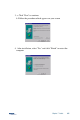

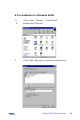
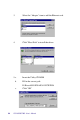
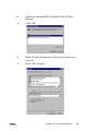

Table Of Contents
- Contents
- Chapter 1 General Information
- Chapter 2 Installation
- 2.1 Jumpers
- 2.2 Connectors
- 2.3 Locating jumpers
- 2.4 Locating connectors
- 2.5 Setting jumpers
- 2.6 CMOS clear (J3)
- 2.7 Installing system memory (DIMMs)
- 2.8 IDE, CDROM hard drive connector (CN16, CN17)
- 2.9 Solid State Disk
- 2.10 Floppy drive connector (CN19)
- 2.11 Parallel port connector (CN21, CN22)
- 2.12 Keyboard and PS/2 mouse connector (CN10)
- 2.13 Front panel connector (CN13)
- 2.14 Power connectors (CN24, CN8, CN26)
- 2.15 ATX power control connector (J4, CN5)
- 2.16 IR connector (CN27)
- 2.17 Audio interfaces (CN2, CN11)(PCM-9550F/9550FM only)
- 2.18 COM port connector (CN20)
- 2.19 VGA interface connections
- 2.20 VGA/TV-Out function select (J1)
- 2.21 Video In/Out interfaces (CN2) (PCM-9550FM only)
- 2.22 Ethernet configuration
- 2.23 Watchdog timer configuration
- 2.24 USB connectors (CN15)
- 2.25 Digital I/O (CN23, CN28: 8 Outputs, 8 Inputs)
- Chapter 3 Software Configuration
- Chapter 4 Award BIOS Setup
- 4.1 System test and initialization
- 4.2 AWARD BIOS setup
- 4.2.1 Entering setup
- 4.2.2 Standard CMOS setup
- 4.2.3 BIOS features setup
- 4.2.4 Chipset features setup
- 4.2.5 Power management setup
- 4.2.6 PnP/PCI configuration
- 4.2.7 Integrated peripherals
- 4.2.8 Load BIOS defaults
- 4.2.9 Change password
- 4.2.10 Auto detect hard disk
- 4.2.11 Save & exit setup
- 4.2.12 Exit without saving
- Chapter 5 PCI SVGA Setup
- Chapter 6 Video (PCM-9550FM)
- Chapter 7 Audio (PCM-9550F/9550FM)
- Chapter 8 PCI Bus Ethernet Interface
- Appendix A Programming the Watchdog Timer
- Appendix B Installing PC/104-Plus Modules
- Appendix C Pin Assignments
- C.1 CPU fan power connector (CN24)
- C.2 Ethernet 10/100Base-T connector (CN6)
- C.3 Audio connector (CN12)(PCM-9550F/9550FM only)
- C.4 CD audio input connector (CN11)(PCM-9550F/9550FM only)
- C.5 Main power connector (CN8)
- C.6 Keyboard and PS/2 mouse connector (CN10)
- C.7 Floppy disk drive connector (CN19)
- C.8 PC/104+ connectors (CN18)
- C.9 IDE HDD connector (CN16, 17)
- C.10 Parallel port connector (CN21, CN22)
- C.11 Front panel connector (J6)
- C.12 USB connector (CN15)
- C.13 LCD inverter backlight connector (CN7)
- C.14 IR connector (CN27)
- C.15 CRT display connector (CN1)
- C.16 Video in/out connector (CN2)
- C.17 24-bit LCD display connector (CN14)
- C.18 36-bit LCD display connector (CN9)
- C.19 Peripheral power connector (CN26)
- C.20 CompactFlash™ card connector (CN30)
- C.21 ATX power feature connector (CN5)
- C.22 Isolated 2 Digital Out (CN28)
- C.23 Digital I/O (CN23)
- C.24 COM port connector (CN20)
- Appendix D System Assignments
- Appendix E Optional Extras for the PCM-9550F/FM/L
- Appendix F Mechanical Drawings
- Table
- Table 2-1: Jumpers
- Table 2-2: Connector Assignments
- Table 2-3: CMOS clear (J3)
- Table 2-4: J8: DOC-2000 address setting
- Table 2-5: Audio power source setting
- Table 2-6: J9: COM2 RS-232/422/485 select
- Table 2-7: Serial port default settings
- Table 2-8: J10: COM1-4 RI settings
- Table 2-9: VGA/TV-Out function select (J1)
- Table 2-10: J2 TV out format select
- Table 2-11: LAN controller power select (J6)
- Table 2-12: Watchdog timer action (J11)
- Table 2-13: Digital output programming
- Table 2-14: Digital input programming
- Table 3-1: Connections to Sharp LM64183P & LM64P89
- Table 3-2: Connections to PLANAR EL
- Table 3-3: Connections to Toshiba LTM10DC042
- Table 3-4: Connections to Sharp LM64C142
- Table 3-5: Connections to Toshiba LTM12C2775A
- Table C-1: CPU fan power connector (CN24)
- Table C-2: Ethernet 10/100Base-T connector (CN6)
- Table C-3: Audio connector (CN12)
- Table C-4: Aux line-in connector (CN11)
- Table C-5: Main power connector (CN8)
- Table C-6: Keyboard and mouse connector (CN10)
- Table C-7: Floppy disk drive connector (CN19)
- Table C-8: PC/104+ connectors (CN18)
- Table C-9: PC/104+ Bus signal assignments (CN18)
- Table C-10: IDE HDD connector (CN16, CN17)
- Table C-11: Parallel port connector (CN21, CN22)
- Table C-12: Front panel connector (J6)
- Table C-13: USB connector (CN15)
- Table C-14: LCD inverter connector (CN7)
- Table C-15: IR connector (CN27)
- Table C-16: CRT display connector (CN1)
- Table C-17: Video in/out connector (CN2)
- Table C-18: 24-bit LCD display connector (CN14)
- Table C-19: 36-bit LCD display connector (CN9)
- Table C-20: Peripheral power connector (CN26)
- Table C-21: CompactFlash Card Connector (CN30)
- Table C-22: ATX power feature connector (CN5)
- Table C-23: Isolated Digital Out (CN28)
- Table C-24: Digital I/O (CN23)
- Table C-25: COM port connector (CN20)
- Table D-1: System I/O ports
- Table D-2: 1st MB memory map
- Table D-3: DMA channel assignments
- Table D-4: Interrupt assignments
- Figure
- Figure 1-1: PCM-9550 dimensions
- Figure 2-1: Locating jumpers
- Figure 2-2: Locating connectors (component side)
- Figure 2-3: Locating connectors (solder side)
- Figure 2-4: Wiring for ATX soft power switch function
- Figure 2-5: CN 23 Digital Input/Output
- Figure 2-6: Digital opto Isolated output block diagram
- Figure 2-7: CN28 Isolated Digital Output
- Figure 4-1: Setup program initial screen
- Figure 4-2: CMOS setup screen
- Figure 4-3: BIOS features setup
- Figure 4-4: Chipset features setup
- Figure 4-5: Power management setup
- Figure 4-6: PnP/PCI configuration
- Figure 4-7: Integrated peripherals
- Figure 4-8: Load BIOS defaults screen
- Figure B-1: PC/104+ module mounting diagram
- Figure B-2: PC/104+ module dimensions (mm) (±0.1)

92 PCA-9550F/FM/L User's Manual
8.1 Introduction
The PCA-9550F/FM/L is equipped with a high performance 32-bit
Ethernet chipset which is fully compliant with IEEE 802.3 100 Mbps
CSMA/CD standards. It is supported by major network operating
systems. It is also both 100Base-T and 10Base-T compatible. The
medium type can be configured via the RSET8139.exe program
included on the utility disk.
The Ethernet port provides a standard RJ-45 jack via an optional
wiring kit. The network boot feature can be utilized by incorporating
the boot ROM image files for the appropriate network operating
system. The boot ROM BIOS files are combined with system BIOS,
which can be enabled/disabled in the BIOS setup.
8.2 Installation of Ethernet driver
Before installing the Ethernet driver, note the procedures below. You
must know which operating system you are using in your PCA-9550F/
FM/L, and then refer to the corresponding installation flow chart.
Then just follow the steps described in the flow chart. You will
quickly and successfully complete the installation, even if you are not
familiar with instructions for MS-DOS or Windows.
Note: The windows illustrations in this chapter are
examples only. You must follow the flow chart
instructions and pay attention to the instructions
which then appear on your screen.
8.2.1 Installation for MS-DOS and Windows 3.1
If you want to set up your Ethernet connection under the MS-DOS or
Windows 3.1 environment, you should first check your server system
model. For example, MS-NT, IBM-LAN server, and so on.
Then choose the correct driver to install in your panel PC.
The installation procedures for various servers can be found on
CD-ROM, the correct path being:
D:\Biscuit\9550F\LAN\8139C\wfw311