
User manual

PCM-4153 User Manual 10
2.6 Flash
The board provides onboard NAND Flash memory to replace CF socket. PCM-4153
support 1 GB flash, flash Endurance about 100K Program/Erase cycles and Data
Retention for 10 Years .
Flash controller with excellent performance and low cost, designed by this controller
do not need to have additional mechanical parts, but have the properties of fully anti
vibration and extremely low power consumption.
On-board flash controller support IDE interface and support to PIO Mode 4.
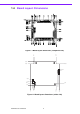
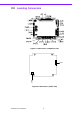
2.7 Parallel Port Connector (CN19)
Normally, the parallel port is used to connect the cable to a printer. The board
includes a multi-mode (ECP/EPP) parallel port accessed via CN19 and a 26-pin flat-
cable connector. You will need an adapter cable if you use a traditional DB-25 con-
nector. The adapter cable has a 26-pin connector on one end, and a DB-25 connec-
tor on the other.
The parallel port is designated as LPT1, and can be disabled or changed to LPT2 or
LPT3 in the system BIOS setup.
The parallel port interrupt channel is designated to be IRQ7.
You can select ECP/EPP/ECP DMA channel via BIOS setup.
2.8 Keyboard and PS/2 Mouse Connector (CN18)
The board provides a keyboard connector that supports both a keyboard and a PS/2
style mouse. In most cases, especially in embedded applications, a keyboard is not
used. If the keyboard is not present, the standard PC/AT BIOS will report an error or
fail during power-on self-test (POST) after a reset. The PCM 4153’s BIOS standard
setup menu allows you to select “All, But Keyboard” under the “Halt On” selection.
This allows no-keyboard operation in embedded system applications, without the
system halting under POST.
2.9 Power Connectors (CN38)
2.9.1 Main Power Connector, +5 V, +12 V (CN38)
Supplies main power +5V to the PCM-4153, and to devices that require +12 V.
2.9.2 Power Reset Button
Momentarily pressing the reset button will activate a reset. The switch should be
rated for 10 mA, 5 V.
2.10 Audio Interfaces (CN34/35)
2.10.1 Audio Connector Audio-out(CN35), Audio-in(CN34)
The board provides all major audio signals on a 8-pin cable connector, These audio
signals include Microphone in (mono), Line in (stereo) and Line out (stereo).