
User manual

7 PCM-4153 User Manual
Chapter 2 Installation
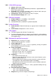
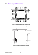
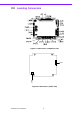
2.2 Connectors
Onboard connectors link the PCM-4153 to external devices such as hard disk drives,
a keyboard, or floppy drives. The table below lists the function of each of the board’s
connectors.
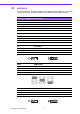
J5 PCI VI/O POWER
Setting Function
(1-2) With +5V
(2-3) With +3.3V (Default)
Table 2.2: Connectors
CN1 ATX feature power connector(optional)
CN4 TFT LCD I/F
CN5 Inverter Power
CN6 SMBus
CN11 IDE
CN15 USB1/2 / CN17 USB 3/4
CN18 KB/MS
CN19 Print Port
CN20 RS422/485
CN23 ISA -5V & -12V Input
CN25 LAN1 / CN26 LAN2
CN27 CRT
CN30 COM1/2/3/4
CN32 Reset / Buzzer pin header
CN33 Battery connector
CN35 AUDIO-OUT / CN34 AUDIO-IN
CN36 GPIO1 / CN37 GPIO2
CN38 Power Input