
User`s manual
CHAPTER 2 INSTALLATION
5
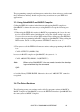
2.2.1. I/O Base Address and Wait State Setting
The I/O ports base address and the number of wait states are selectable by the 8
position DIP switch SW1. The base address can be set anywhere in the I/O address
area from hex 200 to hex 3F8 and the wait states can be set to 0, 2, 4, or 6. Refer to
3 Fig. 2.2. for the locations of the DIP switches SW1. Factory settings of these
switches are hex 2B0 and zero wait state.
This multifunction interface card takes 16 addresses of I/O port following the base
address. The digital output port takes the addresses of BASE+0 and BASE+1 and the
IEEE-488 interface takes the addresses from BASE+8 to BASE+15. When using the
IEEE-488 driver routines, the IEEE-488 interface base address must be set to BASE+8
where the BASE is the set by DIP switch SW1. The default address of the IEEE-488
interface is then hex 2B8.
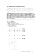
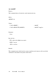
The switch settings for various base addresses and wait states are illustrated as below:
Note : - 0N = 0, 0FF = 1
- 1..8 are switch positions
- W0..W1 correspond to wait state
- A4..A8 correspond to address lines of the PC bus
- * means factory setting
Switch position (SW1)
1 2 3 4 5 Occupied
A8 A7 A6 A5 A4 Addresses
--------------------------------------------------------------------
0 0 0 0 0 200-20F
0 0 0 0 1 210-21F
.
.
.
* 0 1 0 1 1 2B0-2BF
.
.
1 1 1 1 0 3E0-3EF
1 1 1 1 1 3F0-3FF
--------------------------------------------------------------------
Switch position (SW1)
7 8 Wait state(s)
W1 W0
------------------------------------------------
* 0 0 0
0 1 2
1 0 4
1 1 6
------------------------------------------------