PCL-848A/B MULTIFUNCTION IEEE-488 INTERFACE CARD
PCL-848A/B MULTIFUNCTION IEEE-488 INTERFACE CARD USER’S MANUAL This documentation and software routines contained in the PCL848A/B software diskette are copyrighted 1989 by Advantech Co.. Ltd. All rights are reserved. Advantech Co., Ltd. reserves the right to make improvements of the products described in this manual at any time without notice. No part of this manual may be reproduced, copied, translated or transmitted, in any form or by any means without the prior written permission of Advantech Co., Ltd.
Contents 1. GENERAL INFORMATIQN .................................................................. 1 1.1. Introduction to the Product ......................................................................... 1 1.2. Description of the Documentation .............................................................. 2 2. INSTALLATION ...................................................................................... 4 2.1. Inspection .............................................................................
3.4.20. TRIGGER Purpose : ....................................................................................... 38 3.4.21. ERRPTR ........................................................................................................ 39 4. PROGRAMMING TECBNIQUES ...................................................... 41 4.1. 4.2. 4.3. 4.4. 4.5. 4.6. Interactive Data Transfer .......................................................................... 41 Set IEEE-488 Printer ...............................
10. ASCII TABLE ...................................................................................... 74 11. NEC7210 RBAD / WRITE REGISTSR ............................................. 76 12. SUMMARY OF TBE IEEE-488 LIBRARY FUNCTIONS .............
Figures Fig. 2.2 Location of switches and jumpers ................................................... 4 Fig. 7-1 PCL-848A/B Block Diagram ................................................................
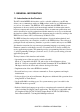
1. GENERAL INFORMATIQN 1.1. Introduction to the Product The PCL-848A/B IEEE-488 interface card is a valuable addition to your PC that allows you to communicate with over 2000 products, made by over 200 manufacturers, in over 14 countries. The IEEE488-1978 standard that this IEEE-488 card implements is the most widely used international standard for information transfer between computer and electronic instruments.
BASICA, BASIC compiler and Quick-BASIC are supported as standard languages. C and Pascal language support packages can be ordered separately as PCL-748-C and PCL-748-P. The software can change the PC printer port to an IEEE-488 device. The PrtSc (print screen) key, all print statements, word processing and spreadsheet programs that use printer driver in BIOS can use IEEE-488 printers. * High speed direct memory access (DMA) with the ability to handle 64K byte arrays.
If you are familiar with the basic concepts of the IEEE-488 bus you may want to begin reading the Section 3. PROGRaI~MING REFERENCE. This section describes the statement syntax and techniques to use the IEEE-488 driver in the firmware. Section 4. PROGRAMMING TECHNIQUES will show you how the functions are used in typical applications and also provide you with some useful program examples for your own applications. All the examples are written in BASICA language.
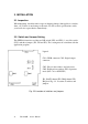
2. INSTALLATION 2.1. Inspection When unpacking, check the unit for signs of shipping damage (damaged box, scratches, dents, etc). If there is any damage to the unit or it fails to meet specifications, notify your localt sales representative immediately. . 2.2. Switch and Jumper Setting This IEEE-488 interface card has two DIP switch (SW1 and SW2), 1 one slide switch (SW3) and three jumpers (JP1, JP2 and JP3). The: setting must be coincident with the application program.
2.2.1. I/O Base Address and Wait State Setting The I/O ports base address and the number of wait states are selectable by the 8 position DIP switch SW1. The base address can be set anywhere in the I/O address area from hex 200 to hex 3F8 and the wait states can be set to 0, 2, 4, or 6. Refer to 3 Fig. 2.2. for the locations of the DIP switches SW1. Factory settings of these switches are hex 2B0 and zero wait state. This multifunction interface card takes 16 addresses of I/O port following the base address.
2.2.2. Firmware Address Setting The IBEE-488 interface driver routine is stored in the on-board i EPROM. The memory address of this firmware can be selected by SW2. The memory segment of the firmware can be from hex 8000 to s hex FC00. Factory setting is hex D000. The range of these locations is out of the 640K system memory of i the IBM PC, PC/ XT and PC/AT. However, choice of this location must be made to avoid any conflict with other interface cards.
2.2.3. Operating Mode Setting SW3 is a slide switch to select the operating mode. When it is set to “A”, this card is compatible with the easy-to-use PCL-748 IEEE-488 interface card except there is no real time clock. When SW3 is set to “N”, this card becomes NI PC-II compatible. 3 It depends on the users which mode is selected. If the software package is already developed for PC-II, then mode “N” can be used to eliminate the software effort.
The IEEE-488 interface card is setup at the factory of default setting: Jumper/Switch Selection Default setting SW1 1-5 SW1 7-8 SW2 SW3 JP1 JP2 JP3 I/O port base address Wait states Firmware base address Operating mode DACK level DRQ level IRQ level Hex 2B0 0 Hex D000 A 1 1 7 Refer to Section 2.2. for other configurations. 2.3.2. Installing the Card into a PC The procedure to install the IEEE-488 interface card is as following: 1.
2.3.3. Function Check Confirm proper operation by connecting an IEEE-488 instrument to i the bus and attempting to operate it with a program written in BASIC. Here is an example procedure using an HP3478A digital voltmeter s and a short BASIC program. 1. Connect the HP3478A DVM to the IEEE-488 bus connector Of this card on the back of the PC with a standard IEEE-488 s cable. On the PCL-848B, the connector is 25 pin D type defined by IEC-625 and a PCL-15488-2 IEC-625 to IEEE-488 cable must be used. 2.
3. PROGRAMMING REFERENCE 3.1. Introduction The PCL-848A/B interface card contains the resident firmware that provides IEEE488 language extensions for your PC. The firmware (software programmed into a readonly-memory) appears transparent to the users and the function inside is called by the IEEE-488 commands. All of the routines in the firmware are written in assembly language to insure maximum data transfer rates. Each routine combines bus error checking.
3.2. Using the BASIC CALL Statement The firmware routines on the IEEE-488 interface card, can be thought of as BASIC language extensions. The extensions consist i of the statements ABORT, CLEAR, ENTER, ENTERA, EOL, INIT, LLO, LOCAL, OUTPUT, OUTPUTA, PPOLL, PPOLLC, PPOLLU, REMOTE, SEND, SPOLL, STATUS, TIMEOUT, TRIGGER and ERRPTR. These routines allow ~ the PC to execute much faster because they are written in assembly language.
Every called routine must define its entry address with an offset from the current segment. For ease of reference all IEEE-488 routine offsets are at three byte increments and start at the top of the segment. For example, the INIT routine is at an offset of 0 (zero), the OUTPUT routine is at an offset of 3, the ENTER routine is at an offset of 6, and so on. Please note that the program offsets must be entered exactly as shown for each interpreter routine.
The programming examples and interpreter routines have been written to work around these limitations and they should not placed any restrictions on your IEEE-488 applications. 3.3. Using QuickBASIC and BASIC Compiler Calling the IEEE-488 routines in the firmware when using BASIC compiler or QuickBASIC is almost the same way as using BASICA except the following two areas. 1.
3.4.1. AHORT Purpose: This command aborts all activities on the interface bus bys Offset : AHORT%=9 Syntax : CALL AHORT% ---BASIC CALL AHSOLUTE(AHORT%) ---BASIC Compiler Parameter: None. Bus Activity : IFC is pulsed for 100 microseconds. REN is set true ATN is set false. Remark : This command can be called only in system controller mode An error will occur if this command is called in the nonsystem control mode.
3.4.2. DEVCLR (Device Clear) Purpose : This command sends a Selective Device Clear (SDC) command to a specified device or sends a Device Clear (DCL) to the interface bus. Offset : DEVCLR%=15 Syntax : CALL DEVCLR%(ADDR%) ---BASIC CALL ABSOLUTE(ADDR%,DEVCLR%) ---BASIC Compiler Parameter : ADDR% - The address of the device to be cleared. If 0 <= ADDR% <= 30, it executes a Selective Device to the i device specified, otherwise, it executes a Device Clear to the bus.
3.4.3. DEVICE Purpose: This command installs an IEEE-488 device driver in place of s the LPT1:, LPT2:, LPT3:, COM1: and COM2: driver. The IEEE-488 devices then can be accessed using the system commandst in MS-DOS. Offset : DEVICE%=57 Syntax: CALL DEVCLR%(ADDR%,PORT%)—BASIC CALL ABSOLUTE(ADDR%,PORT%,DEVCLR%) —BASIC Compiler~ Parameter: ADDR% - The address of the device which is assigned to LPTn: or COMn:. If ADDR% < 0 or ADDR% > 30, the replacement of LPTn: or COMn: is disabled.
3.4.4. ENTER Purpose : This command enters a string from a device or from the interface. Reading iB terminated upon receiving the terminator specified by the EOL command or the maximum length of data bytes is reached. Offset : ENTER%=6 Syntax : CALL ENTER%(ADDR%,DS) ---BASIC CALL ABSOLUTE(ADDR%,D$,ENTER%) ---BASIC Compiler Parameter : ADDR% - Device address. If 0 < ADDR% <= 30, then it enters the string from the specified device, ~ otherwise, it enters the string from the interface.
3.4.5. ENTERA Purpose : This command enters a long string (can be up to 65535 bytes) from a specified device or from the interface. Reading is terminated upon receiving the terminator, or when the specified length is reached, or on timeout. The string is put into the specified segment in the memory. The starting address of the received string has offset 0 in that segment.
Example: 10 DEF SEG=&HD000 ‘ Define location of firmware : 20 ENTERA%=51 : STATUS%=42 ‘ Define routine offset . .
3.4.6. EOL Purpose : This command sets the terminators of input and output strings for the specified device. The terminators of all devices are set to default values if this command is not called. Offset : EOL%=12 Syntax : CALL EOL%(ADDR%,OUTEOL%,OUTEOL$,INEOL%,INEOLBYTE%) ----BASIC CALL ABSOLUTE(ADDR%,OUTEOL%,OUTEOLS,INEOL%,INEOLBYTE%,EOL%) ----BASIC Compiler Parameter : ADDR% - The address of device to be assigned the terminator. The range is from 0 to 30.
3.4.7. INIT Purpose : This aommand initializes the interface card and sets the relative parameters. It can be neglected if the parameters used are all default values. Offset : INIT%=0 Syntax : CALL INIT%(IOPORT%,MYADDR%,SETTING%) ----BASIC CALL ABSOLUTE(IOPORT%,NYADDR%,SETTING%,INIT%) ----HASIC Compiler Parameter : IOPORT% - I/O port of NEC7210, from hex 008 to hex 2F8 by increment of hex 010. The value is the I/O base address plus 8.
For more information about bit 12,14,15 of setting, please refer to Section 5. ADVANCED PROGRANMING TECUNIQUES. Bus Activity : This command takes following action when it is called. 1. Initialize the NEC7210 GP-IB controller. 2. Set relative parameters for the NEC7210. 3. Store the I/O base address, IRQ level and DMA level into working RAM. Examples : 1) Set IEEE-488 interface card to mode : Non-system controller, No IRQ, No DMA. Bus address is 21. I/O port address is hex 2B8 (SW1 is set at hex 2B0).
3.4.8. LLO Purpose : This command executes a Local Lockout (LLO) to disable a device’s front panel. It is received by all devices on the bus, whether or not they are addressed to listen. Offset : LLO%=18 Syntax : CALL LLO% ----BASIC CALL ABSOLUTE(LLO%) ----BASIC Compiler Parameter : None. Bus Activity : ATN is set true. LLO is sent.
3.4.9. LOCAL Purpose : This command executes a Go To Local (GTL) or clears the REN line to enable a device’s front panel controls. Offset : LOCAL%=21 Syntax : CALL LOCAL%(ADDR%) ----BASIC CALL ABSOLUTE(ADDR%,LOCAL%) ----BASIC Compiler Parameter : ADDR% - The address of the device to be set local. If 0 <= addr <=30, then it executes a Go To Local (GTL) command to the specified device. Otherwise, it sets the REN line false (High). Bus Activity : - If 0 <= addr <= 30 ATN is set true. UNL is sent.
3.4.10. OUTPUT Purpose : This command outputs a string to the specified device or to the interface bus. After the string is sent, the terminator 3 specified by the EOL command is sent. Offset : OUTPUT%=3 Syntax : CALL OUTPUTi(ADDR%,D$) ----BASIC CALL ABSOLUTB(ADDR%D$,OUTPUT%) ----BASIC Compiler 3 Parameter : ADDRt - Device address. If 0 <= addr <= 30, then it outputs the string to the specified device. Otherwise, it outputs the string to the interface bus.
3.4.11. OUTPUTA Purpose : This command outputs a long string (can be up to 65535 bytes) to a specified device or to the interface. The output string iB terminated when the length of the output string is approached, or when the bus handshake times out. The output string is in the memory area with the specified segment. The start address of the output string is at offset 0 in that segment.
Example: 10 ‘ This program loads a data file from disk into RAM 20 ‘ and then outputs this data to the IEEE-488 device 8 . . 50 ADDR%=8 60 OPEN “DATA.
3.4.12. PPOLL Purpose : This command conducts a parallel poll of the interface bus. It returns the value (0255) of an eight-bit byte represent- , ing the response of those devices of the interface which have been configured to respond to a parallel poll (see the PPOLLC command). Offset : PPOLL%=24 Syntax : CALL PPOLL%(RESPONSE%) ----BASIC CALL ABSOLUTE(RESPONSE%,PPOLL%) ----BASIC Compiler Parameter : RESPONSE% - An integer equals to the result of parallel polling.
3.4.13. PPOLLC Purpose: This command performs a Parallel Poll Configure. In preparation for a parallel poll command, it enables you to tell a device how to respond to the parallel poll, and on which data line to respond. In general, it enables you to contfigure a parallel poll response byte to reflect the response ri of a desired arrangement of devices. You can define the ~ bits to reflect the responses of particular instruments or the logical-OR of several instrument responses.
Bus Activity: - If O <= addr <= 30 ATN is set true. UNL is sent. LAD is sent. MTA is sent. PPC is sent. PPE is sent. - If ADDR% < 0 or ADDR% >30 ATN is set true. PPC is sent. PPE is sent.
3.4.14. PPOLLU Purpose: This command executes a Parallel Poll Unconfigure. It directs a device to not respond to a parallel poll. It can e be addressed to the interface bus or to a specific device. Offset: PPOLLU%=30 Syntax: CALL PPOLLU%(ADDR%) ----BASIC CALL ABSOLUTE(ADDR%,PPOLLU%) ----BASIC Compiler Parameter: ADDR’ - The address of the device to be unconfigured. If s 0 <= addr <= 30, the specified device is uncon figured. Otherwise, all the devices are unconfigured.
3.4.15. REHOTE Purpose: This command places a device in Remote Mode. It can be addressed to a specific device or to the interface, which just sets the REN line true. Offset: REMOTE%=33 Syntax : CALL REMOTE&(ADDR%) ----BASIC CALL ABSOLUTE(ADDR%,REMOTE%) ----BASIC Compiler Parameter : ADDR% - The address of the device to be set to remote. If 0<=addr<=30, the specified device is set to remote. Otherwise, just the REN line is set true. Bus Activity : - If 0 <= addr <= 30 REN is set true.
3.4.16. SEND Purpose: This command sends user specified IEEE-488 Interface commands to the interface. Eor example, to send an output string to several instruments simultaneously, you can establish multiple listener status with the SEND command, then issue the OUTPUT command with address <0 or >30. Offset: SEND%=36 Syntax: CALL SENDi(CMDS) ----BASIC CALL ABSOLUTE(CMDS,SENDi) ----BASIC Compiler Parameter: CMD$ - Pointer of a string of standard mnemonic IEEE-488 interface commands.
Bus Activity : - The following commands set ATN true then send out the corresponding character. Mnemonic ASCII (Hex) UNL ? (3F) UNT GET DCL GTL (5F) (08) (14) Mnemonic ASCII SDC SPD SPE TCT *MLA 5 (hex) (04) (19) (18) (09) P PPD PPU (01) (05) (70) (15) *MTA U LLO (35) (55) (11) * My address = 21 The following commands take some actions other than sending characters. LISTEN Take following values as listener address. TALK Take following values as talker address.
3.4.17. SPOLL Purpose : This command conducts a serial poll of the interface bus. It returns the value (0255) of an eight-bit byte representing the device’s status. Offset : SPOLL%=39 Syntax : CALL SPOLL%(ADDR%,RESPONSE%) ----BASIC CALL ABSOLVTE(ADDR%,RESPONSE%,SPOLL%) ----BASIC Compiler Parameter : ADDR% - The address of the device to be serial polled. Must be within 0 and 30. RESPONSE% - An integer with the value 0-255 of an eight bit byte representing the status of the device specified.
3.4.18. STATUS Purpose : Purpose : This command reads the status from the interface and returns this value to the calling statement. Offset : STATUS%=42 Syntax : CALL STATUS%(CONDITION%,5%) CALL ABSOLUTE(CONDITION%,5%,5TATUS%) ----BASIC ----BASIC Compiler Parameter : CONDITION% - This number specifies which status is read. 0 - 7 : NEC7210 read register 0 - 7. 8 : Error Number of last called command. 9 : Count of string bytes that are output or entered. 10 : Timeout interval in milliseconds.
3.4.19. TIMEOUT Purpose : Purpose : This command sets the timeout period. When the bus handshake is stuck, the called I/O functions will terminate at the time specified and the timeout flag will be set. Offset : TIMEOUT%=45 Syntax : CALL TIMEOUT%(T%) CALL ABSOLUTE(T%,TIMEOUT%) ----BASIC ----BASIC Compiler Parameter: T% T% = 0 Disable the timeout command. T% = 1 to 32767 Timeout period is T% units. T% = -1 to -32767 Timeout period is (65536+T%) units. Bus Activity : None. Remark : 1.
3.4.20. TRIGGER Purpose : Purpose : This command sends a Group Execute Trigger (GET) to a device or to the interface bus. Offset : TRIG%=48 Syntax: CALL TRIGi(ADDRi) CALL AHSOLUTE(ADDR’,TRIG%) ----BASIC ----BASIC Compiler Parameter : ADDRi - The address of the specified device to be triggered. If 0 <= addr <= 30, the specified device is triggered. Otherwise, all the listeners of the bus are triggered. Hus Activity : - If 0 <= addr <= 30 ATN is set true. UNL is sent. LAD is sent. MTA is sent.
3.4.21. ERRPTR Purpose : This command assigned variables for error number and count of string bytes. Offset: ERRPTR%=60 Syntax : CALL ERRPTR%(IOERR%,IOCOUNT%) ----BASIC CALL ABSOLUTE(IOERR%,IOCOUNT%,ERRPTR%) ----BASIC Compiler Parameter : IOERR% - Variable which represents the error number of last called command. IOCOUNT% - Variable which represents the count of string bytes that are outputed or entered. Bus Activity : None.
Example : 10 20 30 40 50 60 70 80 85 90 100 110 120 130 160 170 40 DEF SEG=&HD000 INIT%=0:OUTPUT%=3:ENTER%=6:ERRPTR%=60 ADDR%=23 CALL ERRPTR%(IOERR%,IOCOUNT%) TMPS=”FlRAT3NS” CALL OUTPUT%(ADDR%,TMP$):GOSUB 100 ANs$=sPACE$(40) CALL ENTER%(ADDR%,ANS$):GOSUH 100 PRINT ANS$ STOP ‘Error number and string counts check routine PRINT “TBE COUNT OF STRING BYTES = “;IOCOUNT% IF IOERR%=0 TEEN PRINT “NO ERROR” IF IOERR%=1 TREN PRINT “3ANDSBAKE TIMEOUT” RETURN END PCL-848AB User's Manual
4. PROGRAMMING TECBNIQUES 4.1. Interactive Data Transfer 10 20 40 50 70 80 90' 100 110 120 130 140 150 160 170 180 190 200 210 220 230 240 250 260 270 280 290 310 320 330 340 350 360 370 380 390 400 410 'FILE NAME : EXAMPLE.1 'Program Example : INTERACTIVE DATA TRANSFER 'Purpose : This program outputs data strings entered by users and enters data from the IEEE-488 bus. ' 'Initialization LIN.
420 430 440 450 460 430 490 500 510 520 530 540 550 560 570 580 590 600 610 620 630 640 650 660 670 680 690 700 710 720 730 740 750 760 770 780 790 800 810 820 830 42 'OUTPUT UTILITY ' TMP$=SPACE$(80) IF 22-LIN.Y<6 TREN CLS:LIN Y=1 LOCATE 22,1,0:PRINT “ “;SPACE$(79):LOCATE LIN.Y,1 INPUT “To which address 7 “,ADDR LINE INPUT ‘’OUTPUT string 7 “,TNP$ E.FG%=0 : CALL OUTPUT%(ADDR%,TMP$) GOSUB 710 IF S%=0 THEN PRINT “Data transmitted 1” PRINT : PRINT : LIN.
4.2. Set IEEE-488 Printer 10 20 30 40 50 70 80 90 100 110 120 130 140 150 170 180 190 200 220 230 250 260 270 290 300 320 330 340 350 360 370 380 390 'FILE NAME : EXAMPLE.2 ' Program Example : SET IEEE-488 PRINTER ' 'Purpose : This program converts an IEEE-488 printer to a 'PC system printer ' 'Initialization CLS DEF SEG=&HD000 DEVICE%=57 Enter the IEEE-488 printer setting INPUT “Enter the IEEE-488 printer address ? “,ADDR% IF ADDR&<0 OR ADDR~~>30 THEN PRINT “Bad entry.
4.3. Voltage Measurement with a DVM 10 20 30 40 50 60 70 80 90 100 110 120 130 140 160 170 180 190 200 210 220 230 240 260 270 280 290 300 310 320 330 340 350 360 370 380 390 400 410 420 430 440 450 460 470 480 44 'FILE NAME : EXAMPLE.3 'Program Example : VOLTAGE MEASUREMENT WIT)3 A DVM ' 'Purpose : This program measure 10 voltage readings 'and displays them ' 'Remark : This program is written for the HP3478A DVM.
4.4. AD500 PMU Programming 10 20 30 40 50 60 70 80 90 100 110 120 125 130 140 150 160 170 180 190 200 210 220 230 240 250 260 270 280 290 300 310 320 330 340 350 360 370 380 390 400 410 'FILE NAME : EXAMPLE.4 'Program Example : AD500 PMU PROGRAMMING ' 'Purpose : This program measures 16 channel of voltages and 'display them. If the voltage of any channel is 'greater than a certain level then it close a 'relay to drive an alarm.
420 430 440 450 460 470 480 490 500 510 520 530 550 560 'Measurement start ' ALARM%=0 FOR I=0 TO 15 D$=”DW0,”+STR$(I) ' CALL OUTPUT%(ADDR500%,D$) ‘ Close channel I. FOR K-1 TO 10 : NEXT K ‘ Delay for the relay operation. CALL TRIGGER%(ADDR3478%) ‘ Trigger the DVM. D$=SPACES(40) 540 CALL ENTER%(ADDR3478%,DS) ‘ Enter DVM reading GOSUB 770 ‘ Error check IF ER%0 THEN PRINT “Error when setting DVM.” : END 570 ‘ 580 V(I)=VAL(D$) PRINT I,V(I), IF V(I)>V.
4.5. Multiple Device Triggering 10 20 30 40 50 60 70 80 90 100 110 120 130 140 150 160 170 180 190 200 210 220 230 240 250 260 270 280 290 300 310 320 330 340 350 360 370 380 390 400 410 'FILE NAME : EXAMPLE.5 'Program Example : MULTIPLE DEVICE TRIGGERING ' 'Purpose : This program triggers 2 voltmeters at the same 'time to make the measurement simultaneously. ' 'Remark : This program is written for the HP3478A DVM.
420 430 440 450 460 470 480 490 500 510 520 530 540 550 560 570 590 600 610 620 630 48 ' D2$=SPACE$(40) CALL ENTER%(ADDR2%,D$) ‘ Enter DVM #2 reading GOSUB 550 ‘ Error check IF ER%<>0 TEEN PRINT “Error when reading DVM #2.
4.6. Interrupt Handling 10 20 30 40 50 60 70 80 90 100 110 120 130 140 150 160 170 180 190 200 210 220 230 260 270 280 290 300 310 320 330 340 350 360 370 380 390 400 410 420 430 440 450 'FILE NAME : EXAMPLE.6 'Program Example : INTERRUPT HANDLING ' 'Purpose : This program measures 100 voltage readings and 'displays them. It also goes to service 'subroutines when interrupts happen. ' 'Remark : The interrupt handing is for the Advanced BASIC 'Version A3.00 and higher only.
460 470 480 490 500 450 510 520 530 540 550 560 570 580 600 610 620 630 640 650 660 670 680 690 700 710 720 730 740 750 760 770 780 790 800 810 820 830 840 850 860 50 'Measurement start ' FOR I=1 TO 100 CALL TRIGGER%tADDR%) ‘ Trigger the DVM.
5. ADVANCED PROGRAMM1N TECBNIQUES 5.1. Direct Memory AcceAs (DMA) Direct memory acaess (DHA) improves system performance by allow- ~ ing external devices to directly transfer information to or from 3 the system memory without operation of the system CPU. Any I/O ~ port can source data for DMA and any read-write memory location ~¤ can receive data. The IEEE-488 interface data transfer can be programmed to proceed with or without DMA.
2) The DMA operating mode (single, demand, block, and cascade). 3) Autoinitialization (enabled or disabled). 4) Address register direction (increment or decrement). A little additional explanation is required to understand these key operating conditions. This interface allows you to choose from three of the four possible DMA channels. Channel 0 is used by the PC’s memory refresh controller, so channels 1, 2, and 3 are the only ones available to the peripherals.
The DMA operation of this IEEE-488 interface is quite transparent to users. Once you select the DMA mode by calling INIT routine, all further data transfer proceeds in this mode. Bowever, when you select block-transfer mode, the DMA channel 0 memory refresh may be held long enough to corrupt RAM memory content. Do not use block-transfer mode unless you have confidence that the data transfer will be completed within the time limits of memory refresh.
5.2. Transfer Speed The data transfer speed is determined by several factors: 1) The instruction execution speed of the computers. (4.77 MBz PC/XT to 16 MHz PC/AT to ?) 2) The software overhead. 3) The interface chip operating speed. 4) The clock rate of the DMA chip. (3 to 8 MBz) 5) DMA operating mode. 6) The operating speed of other processors that may be occupying the data bus. (e.g. 8087 coprocessor) 7) The speed of handshake of the peripheral devices. 8) The IEEE-488 cable length and capacitance.
5.3. Interrupt The interface has the capability to interrupt the PC’s processor when certain event happen. Dowever, most of the version of BASIC language in MS-DOS operating system only handles the interrupts from keyboard, light pen, communication port, game port and BASIC error. To use interrupt capability in BASIC, the software can replace Function Key 19 and 20 interrupts and can add some ERROR’s to inform BASIC that there is an interrupt from the IEEE488 interface.
5.4. Hore about the SEND Command The SEND routine allows the user to control the IEEE-488 interface directly. Therefore, some unusual functions of the IEEE-488 function can be done by calling SBND. An example is PASSING CONTROL to another device. This can be done by executing the following statements. This example passes control to device 22. SEND%=36 CND$=”UNL UNT TALK 22 TCT” CALL SEND%(CMD$) Some instruments use secondary addressing technique.
6. DIGITAL OUTPUT The PCL-848A/B provides 16 digital output channels. These i digital output channels use the I/O port registers at address BASE+0 and BASE+1. The register’s data format is listed below. BASE + O (write port) D7 D6 DS D4 D3 D2 D1 DO D/O low byte D07 D06 D05 D04 D03 D02 DO1 D00 BASE + 1 (write port) D7 DS D4 D3 D2 D1 DO D/O high byte D015D014 D013 D012 DOll D010 DO9 D08 D6 It is fairly straight forward to use your PCL-848A/B digital ~ output functions.
7. TBEORY OP OPERATION 7.1. Introduction This section describes the operation theory of this IEEE-488 t interface card. A thorough understanding of the theory will increase its usefulness and help avoid future problems. 7.2. Block Diagram Description Figure 7.1. is the block diagram of this interface card. The i interface transfers data in a bi-directional fashion between the PC-Bus and the IEEE-488 instrument bus. The IEEE-488 bus driver is stored in the on-board ROM.
Fig.
8. TROUBLESHOOTING 8.1. Introduction This section provides information on maintaining, troubleshooting and repairing the IEEE-488 interface card. 8.2. Periodia Maintenance The IEEE-488 interface card has no internal adjustment and does not require periodic calibration. Bowever, the following actions are recommended for preventive maintenance on a once-a-year basis (or more often, in high humidity environments).
SYmDtom Possible Fault Check Computer hangs up when calling driver routine Bad connections between golden fingers and PC slot Clean wax on golden fingers On-board firmware address switch setup not the same as software setup Change the switch setup or the softis ware The firmware address or I/O address setconflict with other add-on cards Change the firmware or I/O address settings tings Instrument does not Wrong instrument Instrument address response address setting Bad bus connections Check
8.4. Part List Item No. Oty Description C1-C6, C8-C21 20 0.1 microfarad capacitors C7,C22, C23 3 10 microfarad capacitors C24 1 470 picofarad capacitor R1 1 0 ohm resistor R2 1 51 ohm resistor RP1,RP3 2 4.7 Rohm resistor array (9 pin) RP2 1 4.
Item No.
9. BUS TUTORIAL 9.1. General BUB DeBCriPtiOn The IEEE-488 bus is easy to use and allows great flexibility in data communications between independent devices. These features have made it one of the world’s most popular methods for connecting multiple devices to one interface. The IEEE-488 bus’s popularity comes from its ability to act as an interface between the computer and the computer’s peripherals.
Operationally, the interface is thoughtfully supported with professional software support package. The software provides high level language extensions that support IEEE-488 bus data and i command transmission and reception. The function mnemonics are identical to those found in the IEEE-488 standard. These mnemonics are used by most manufacturers of IEEE-488 compatible equip ment.
2) TALKER. A device capable of transmitting data to other devices. Typical talkers are voltmeters,counters, audio analyzers and many other measurement instruments. 3) CONTROLLER. A device capable of managing communications over the IEEB-488 bus such as addressing and sending commands. A PC with the IEEE-488 interface is typically a controller. An IEEE-488 bus system allows only one device at a time to active talker, but it allows multiple listeners receiving the same data at the same time.
9.2.2. IEC-625 Connector Pin Assignment The IEC-625 standard uses 25 pin D type connector as the standard and the signal assignment is: DATA Lines Pin No. ---------------------------------DIO1 1 DI02 2 DI03 3 DI04 4 DI05 14 DI06 15 DI07 16 DI08 17 MANAGEMENT Lines Pin No. ------------------------------------------------IFC 10 REN 5 ATN 12 SRQ 11 EOI 6 HANDSHAKE Lines Pin No. ------------------------------------------------DAV 7 NRFD 8 NDAC 9 9.3.
9.4. Bus Commands In COMMAND mode, bus commands can be placed on the bus and sent to all devices. These commands have the same meaning regardless of the kind of device. Each device is designed to respond to those commands that have a useful meaning to the device and will ignore all others. The operating manual of each device will state those commands it can recognize.
2) If a service request i8 present, the controller sets the serial poll mode. The serial poll mode is initiated by the r controller sending the command SPE (Serial Poll Enable). 3) The controller sequentially polls those devices that may a have requested service. Each polled device responds with the status byte. The controller then checks the bit 6 (weight 64) of the byte to see if service was requested by this device. 4) For each device that has requested service, the controller takes appropriate action.
70 PCL-848AB User's Manual
9.8. Randshake Lines Each character byte transferred on the bus data lines employs the three wire handshake sequence. This sequence has the following characteristics: 1) Data transfer is asynchronous. Data can be transferred at any rate suitable for the devices operating on the bus. The devices wait for others to complete a byte transfer. 2) Devices with different input and output speeds can be interconnected. Data transfer rate is determined by the 3 slowest active device.
Handshake Timing Sequence 72 PCL-848AB User's Manual
9.9. Other Bus Lines The three remaining bus lines are: 1) REN (Remote Enable) The system controller sets REN low and then addresses the devices to listen before they will operate under remote control. 2) IFC (Interface Clear) Only the system controller can activate this line. When IFC is set true, all talkers, listeners and active controllers go to their inactive states.
10.
CHAR BINARY UEX DEC COMMAND @ A B C D E F G H I J K L M N O P Q R 5 T U V W X Y Z [ \ ] ^ _ 1000000 1000001 1000010 1000011 1000100 1000101 1000110 1000111 1001000 1001001 1001010 1001011 1001100 1001101 1001110 1001111 1010000 1010001 1010010 1010011 1010100 1010101 1010110 1010111 1011000 1011001 1011010 1011011 1011100 1011101 1011110 1011111 40 41 42 43 44 45 46 47 48 49 4A 4H 4C 4D 4E 4F 50 51 52 53 54 55 56 57 58 59 SA SB SC SD SE SF 64 65 66 67 68 69 70 71 72 73 74 75 76 77 78 79 80 81 82 83
11.
12. SUMMARY OF THE IEEE-488 LIBRARY FUNCTIONS Routins Offset Parameters ABORT 9 None DEVCLR 15 ADDR% DEVICE 57 ADDR%,PORT% ENTER 6 ADDR%,D$ Enters data from a device. ENTERA 51 ADDR%,DATASEG%, Enters a long string from a EOL 12 ADDR%,OVTEOL%, Sets the terminators of input OUTEOL$,INEOL%, and output string of a device LENGTB% Activity Aborts all bus activity by pulsing the IFC line. Device clear or selective device clear. Replaces an LPTn: or COMn: port with an IEEE-488 device.
Routins Offset Parameters SPOLL 39 ADDR%,RESPONSE% STATUS 42 CONDITION%,5% TIMEOUT 45 T% TRIGGER 48 ADDR% ERRPTR 60 IOERR%,IOCOUNT% 78 PCL-848AB User's Manual Activity Serial Poll. Reads the status of the interface. Sets timeout interval. Triggers a device or devices Assign variables for error number and count of string bytes.