
Specifications


University of Hertfordshire
24
Chapter Five: SYSTEM SETTING
This chapter will introduce the whole process about system setting including: the
installation of PCL 848A/B GPIB Card, and its initial settings, and the
installation and configuration of sgpib driver.
5.1 Installation and Configuration of PC-LAB GPIB Card
5.1.1 Switch and Jumper Setting
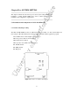
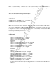
The PCL 848A/B GPIB Card has two DIP switch (SW1 and SW2), one slide switch (SW3) and
three jumpers (JP1, JP2 and JP3). The setting must be coincident with the application program.
CN1: GP-IB connector CN2: Digital output connector
SW1: I/O port base address and wait states
SW2: Firmware base address
SW3: Operation mode (PCL-748 or NI PCÑI I)
JP1: DACK channel
JP2: DRQ channel
JP3: IRQ level
Figure 5.1 Location of switches and jumpers