
User manual


PCL-818 Series User Manual 52
C.7 MUX Scan Channel Status — BASE+02H
Read register BASE+02H to get the current multiplexer (MUX) channel.
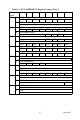
Table C-6 Register for MUX Scan Channel Status
CC3 ~ CC0 Current channel number
CC0 the least significant bit (LSB) of the stop channel
CC3 the most significant bit (MSB)
C.8 Digital I/O Registers - BASE + 03/0BH
The PCL-818HD/HG/L provides 16 digital input channels and 16 digital
output channels. You read digital input data from registers BASE+03H
and BASE+0BH. After the read operation the input lines go to three-state
(data is not latched).
You write digital output data to registers BASE+03H and BASE+0BH.
The registers latch the output value (you cannot read it back).
Using the PCL-818HD/HD/L's input and output functions is fairly
straightforward. Chapter 3 gives some ideas for digital signal connec-
tions.
Table C-7 Register for Digital Output
DO15 ~ DO0 Digital output data
DO0 the least significant bit (LSB) of the DO data
DO15 the most significant bit (MSB)
Read MUX scan channel status
Bit # 7 6 5 4 3 2 1 0
BASE + 02H CC3 CC2 CC1 CC0
Write Digital Output
Bit # 7654 3210
BASE + 03H DO7 DO6 DO5 DO4 DO3 DO2 DO1 DO0
BASE + 0BH DO15 DO14 DO13 DO12 DO11 DO10 DO9 DO8