
User manual


PCL-818 Series User Manual 48
C.4 Software A/D Trigger — BASE+00H
You can trigger an A/D conversion from software, the card's on-board
pacer or an external pulse. If you select software triggering, a write to the
register BASE+00H with any value will trigger an A/D conversion.
Bits 1 and 0 of register BASE+09H select the trigger source. See pages
57 and 58 for BASE+09H register layout and programming information.
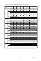
Table C-3 Register for Software A/D Trigger
C.5 A/D RangeControl — BASE+01H
Each A/D channel has its own individual input range, controlled by a
range code stored in on-board RAM. If you want to change the range
code for a given channel, select the channel as the start channel in register
BASE+02H, MUX scan (described in the next section), then write the
range code to bits 0 to 3 of BASE+01H.
Table C-4 Register for A/D Range Control
G3 ~ G0 A/D range control
G0 the least significant bit (LSB) of the A/D range
G3 the most significant bit (MSB)
Write Software A/D trigger
Bit # 7 6 5 4 3 2 1 0
BASE + 00H X X X X X X X X
Write A/D range control
Bit # 7 6 5 4 3 2 1 0
BASE + 01H X X X X G3* G2* G1 G0