
User manual


31 Chapter 3
3.3.2 I/O Connector Signal Description
Table 3-9 I/O Connector Signal Descriptions
Analog Input Connection
The PCL-818HD/HG/L supports either 16 single-ended or 8 differential
analog inputs. Switch SW2 selects the input channel configuration.
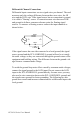
Single-ended Channel Connections
Single-ended connections use only one signal wire per channel. The volt-
age on the line references to the common ground on the card. A signal
source without a local ground is called a "floating" source. It is fairly sim-
ple to connect a single ended channel to a floating signal source. A stan-
dard wiring diagram looks like this:
Signal Name Reference Direction Description
A/D S <0..15> A.GND Input Analog input (single-ended), channels 0 through
15.
A/D H <0..7> A.GND Input Analog input high (differential), channels 0
through 7.
A/D L <0..7> A.GND Input Analog input low (differential), channels 0 through
7.
D/A A.GND Output Analog output
AGND - - Analog Ground. The two ground references
(A.GND and D.GND) are connected together on
the PCL-818HD/HG/L card.
D/O D.GND Output Digital output, channels 0 through 15.
D/I D.GND Input Digital input, channels 0 through 15.
CLK D.GND Input Clock input for the 8254.
GATE D.GND Input Gate input for the 8254.
OUT D.GND Output Signal output for the 8254.
VREF D.GND Output Voltage reference.
REFIN D.GND Input External voltage reference input.
S1-S4 D.GND Output Daughterboard channel select.
DGND - - Digital Ground. The two ground references
(A.GND and D.GND) are connected together on
the PCL-818HD/HG/L card.
+12V D.GND Output +12 V
DC
Source (from ISA bus directly with FUSE
protection).
+5V D.GND Output +5 V
DC
Source (from ISA bus directly with FUSE
protection).
NC - - No connection.
Signal Input
+
Vs
-
A.GNDA.GND
A.GND
To A/D