
User manual


25 Chapter 3
Table 3-3: Jumper JP11 Settings
When you set JPI1 to INT, the D/A converter takes its reference voltage
input from the card's on-board reference. Jumper JP10 selects either -5 V
or -10 V on-board reference voltage. With JP11 set to INT the D/A chan-
nel has an output range of 0 to +5 V or 0 to +10 V, respectively.
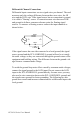
When you set JP11 to EXT, the D/A converter takes its reference voltage
input from pin 31 of connector CN3.You can apply any voltage between -
10 V and +10 V to this pin to function as the external reference. The ref-
erence input can be either DC or AC (<100 KHz).
When you use an external reference with voltage Vref you can program
the D/A channel to output from 0 V to -Vref, you can also use the D/A
converter as a programmable attenuator. The attenuation factor between
reference input and analog output is:
Attenuation factor = G / 4095
Where G is a value you write to the D/A registers between 0 and 4095.
For example, if you set G to 2048, then the attenuation factor is 0.5. A
sine wave of 10 V amplitude applied to the reference input will generate a
sine wave of 5 V amplitude on the analog output.
Jumpers Function Description
JP11 External
Internal (default)