
User manual


The PCI-1733 Interrupt Control Register controls the status of four interrupt
signal sources (IDI0, IDI1, IDI16, DI17). The user can clear the interrupt by
writing its corresponding value to the Interrupt Control Register, as shown in
below table.
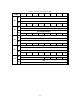
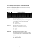
Table C-11 Register for interrupt control
Write Interrupt Control Register
Bit # 7 6 5 4 3 2 1 0
BASE + 8H IDI17EN IDI16EN IDI1EN IDI0EN
BASE + CH IDI17RF IDI16RF IDI1RF IDI0RF
BASE + 10H
IDI17CLR IDI16CLR
IDI1CLR IDI0CLR
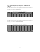
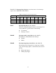
IDInCLR Interrupt clear control bits (n = 0, 1, 16, 17)
This bit must first be cleared to service the next interrupt.
0 Don’t care
1 Clear the interrupt
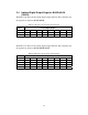
IDInEN Interrupt enable control bits (n =0, 1, 16, 17)
Read this bit to Enable/Disable the interrupt.
0 Disable
1 Enable
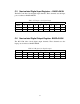
IDInRF Interrupt triggering control bits (n = 0, 1, 16, 17)
The interrupt can be triggered by a rising edge or falling
edge of the interrupt signal, as determined by the value in
this bit.
0 Rising edge trigger
1 Falling edge trigger
56