
User manual

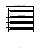

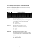


The PCI-1733 Interrupt Status Register control the status of four interrupt
signal sources (IDI0, IDI1, IDI16, IDI17).
Table C-9 Register for interrupt status
Read Interrupt Status Register
Bit # 7 6 5 4 3 2 1 0
BASE + 8H IDI17EN IDI16EN IDI1EN IDI0EN
BASE + CH IDI17RF IDI16RF IDI1RF IDI0RF
BASE + 10H IDI17F IDI16F IDI1F IDI0F
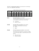
IDInF Interrupt flag bits (n = 0, 1, 16, 17)
This bit is a flag indicating the status of an interrupt. User
can read this bit to get the status of the interrupt
0 No interrupt
1 Interrupt occurred
IDInEN Interrupt enable control bits (n = 0, 1, 16, 17)
Read this bit to Enable/Disable the interrupt.
0 Disable
1 Enable
IDInRF Interrupt triggering control bits (n = 0, 1, 16, 17)
The interrupt can be triggered by a rising edge or falling
edge of the interrupt signal, as determined by the value in
this bit.
0 Rising edge trigger
1 Falling edge trigger
54