
User manual


Isolated Digital Output
Each of the 16 isolated digital output channels comes equipped with a
darlington transistor. Every eight ouput channels share common
emitters and integral suppression diodes for inductive load, activated
by connecting PCOM to VDD. (Channels 0 ~ 7 use PCOM0. Channels
8 ~ 15 use PCOM1.)
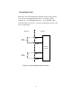
If the external voltage (5 ~ 40 V) is connected to each isolated output
channel (IDO) and its isolated digital output turns on (150 mA per
channel maximum), the card's current will sink from the external
voltage. The current through EGND should not exceed 2.4 A.
If the current for all channels combined exceeds 2 A, CN5 must be
connected to the external ground to share the extra current. The
following figureshows how to connect an external output load to the
card's isolated
outputs.
Internal External
IDO0
IDO1
IDO2
IDO3
IDO4
IDO5
IDO6
IDO7
EGND
Isolated
Circuit
PCOM
Relay
NO
NC
Common
Diode
VDD
5~40V
Figure 3-9: Isolated digital output connection
32