
User manual

PCI-7020 User Manual 32
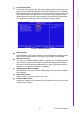
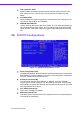
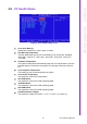
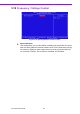
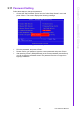
Figure 3.8 Super I/O device
! Onboard Serial Port 1
The settings are “3F8/IRQ4”, “2F8/IRQ3”, “3E8/IRQ4”, “2E8/IRQ3”, and “Dis-
abled” for the on-board serial connector.
! Onboard Serial Port 2
The settings are “3F8/IRQ4”, “2F8/IRQ3”, “3E8/IRQ4”, “2E8/IRQ3”, and “Dis-
abled” for the on-board serial connector.
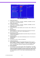
! UART Mode Select
This item allows you to select UART mode. The choices: “IrDA”, “ASKIR”, and
“Normal”.
! RxD, TxD Active
This item allows you to determine the active level of the RxD and TxD serial
lines. The Choices: “Hi, Hi”, “Lo, Lo”, “Lo, Hi”, and “Hi, Lo”.
! IR Transmission Delay
This item allows you to enable/disable IR transmission delay. The choices are
“Enabled” and “Disabled”.
! UR2 Duplex Mode
This item allows you to select the IR half/full duplex function. The choices are
“Half” and “Full”.
! Use IR Pins
The choices are “RxD2, TxD2” and “IR-Rx2Tx2”.
! Onboard Parallel Port
This field sets the address of the on-board parallel port connector. You can
select “378/IRQ7”, “278/IRQ5”, “3BC/IRQ7”, or “Disabled”. If you install an I/O
card with a parallel port, make sure there is no conflict in the address assign-
ments. The single board computer can support up to three parallel ports.
! Parallel Port Mode
This field allows you to set the operation mode of the parallel port. The setting
“Normal” allows normal speed operation, but in one direction only. “EPP” allows
bi-directional parallel port operation at maximum speed. “ECP” allows the paral-
lel port to operate in bi-directional mode and at a speed faster than the maxi-
mum data transfer rate. “ECP + EPP” allows normal speed operation in a two-
way mode.