
User manual


PCI-7020 User Manual 14
2.1 Introduction
You can access most of the connectors from the top of the board while it is installed
in the chassis. If you have a number of cards installed or have a packed chassis, you
may need to partially remove the card to make all the connections.
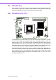
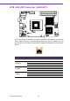
2.2 Parallel Port (LPT1)
The parallel port is normally used to connect the single board computer to a printer.
The PCI-7020 includes an onboard parallel port, accessed through a 26-pin flat-
cable connector, LPT1. The card comes with an adapter cable which lets you use a
traditional DB-25 connector. The cable has a 26-pin connector on one end and a DB-
25 connector on the other, mounted on a retaining bracket. The bracket installs at the
end of an empty slot in your chassis, giving you access to the connector.
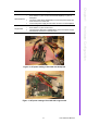
To install the bracket, find an empty slot in your chassis. Unscrew the plate that cov-
ers the end of the slot. Screw in the bracket in place of the plate. Next, attach the flat-
cable connector to LPT1 on the CPU card. Wire 1 of the cable is red or blue, and the
other wires are gray. Make sure that wire 1 corresponds to pin 1 of LPT1. Pin 1 is on
the upper right side of LPT1.