User Manual PCI-7020 PCI Half-sized Intel® LGA775 Processor Card with VGA/Single Gigabit LAN
Copyright The documentation and the software included with this product are copyright 2009 by Advantech Co., Ltd. All rights are reserved. Advantech Co., Ltd. reserves the right to make improvements in the products described in this manual at any time without notice. No part of this manual may be reproduced, copied, translated or transmitted in any form or by any means without the prior written permission of Advantech Co., Ltd. Information provided in this manual is intended to be accurate and reliable.
A Message to the Customer Advantech Customer Services Each and every Advantech product is built to the most exacting specifications to ensure reliable performance in the harsh and demanding conditions typical of industrial environments. Whether your new Advantech equipment is destined for the laboratory or the factory floor, you can be assured that your product will provide the reliability and ease of operation for which the name Advantech has come to be known. Your satisfaction is our primary concern.
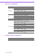
Memory Compatibility Brand Apacer(RoHS) DSL Kingston(RoHS) Transcend(RoHS) Size Speed Type Memory 512 MB DDR2 533 DDR2 ELPIDA E5108AG-5C-E (64x8) 512 MB DDR2 667 DDR2 ELPIDA E5108AG-6E-E (64x8) 1 GB DDR2 533 DDR2 SAMSUNG K4T51083QB-ZKD5 (128x4) 1 GB DDR2 533 DDR2 ELPIDA E5108AGBG-6E-E (64x8) 1 GB DDR2 667 DDR2 ELPIDA E5108AGBG-6E-E (64x8) 2 GB DDR2 667 DDR2 SEC K4T1G08400 (128x8) 512 MB DDR2 533 DDR2 infineon HYB18T512 800AF37 FSS43331 (64x8) 1 GB DDR2 533 DDR2 ELPIDA
Processor Support Intel Core™ 2 Duo Desktop Processor Long-term supported P/N: E7400, E6400, Intel® Pentium® Dual-Core Desktop Processor E4300, E2160, Celeron 440 Intel Celeron® Processor 400 Intel Pentium D Processor Intel Pentium 4 Processor Intel Celeron D Processor Note! PCI-7020 CPU cooler (p/n:1960035861N000), It must use the CPU thermal design power lower than 65 Watt.
Initial Inspection Before you begin installing your single board computer, please make sure that the following materials have been shipped: ! ! ! ! ! ! ! ! ! ! ! ! ! ! PCI-7020 Intel® LGA775 processor-based single board computer 1 PCI-7020 user manual 1 CD with driver utility and manual (in PDF format) 2 Power cable 12P / Big 4P 1 Dual COM cable 2.0 mm pitch 1 Serial ATA HDD data cable 1 Serial ATA HDD power cable 1 Printer port cable 2.
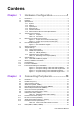
Contens Chapter 1 Hardware Configuration......................1 1.1 1.2 1.3 Introduction ............................................................................................... 2 Features .................................................................................................... 2 Specifications ............................................................................................ 3 1.3.1 System ......................................................................................
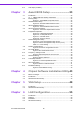
Chapter 2.15 Case Open (JCASE1)............................................................................. 21 3 Award BIOS Setup ............................ 23 3.1 Introduction ............................................................................................. 24 3.1.1 CMOS RAM Auto-backup and Restore ...................................... 24 Entering Setup ........................................................................................ 24 Figure 3.
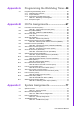
Appendix A Programming the Watchdog Timer..59 A.1 Programming the Watchdog Timer ......................................................... 60 A.1.1 Watchdog timer overview............................................................ 60 A.1.2 Jumper selection......................................................................... 60 A.1.3 Programming the Watchdog Timer ............................................. 60 Table A.1: Watchdog Timer Registers ....................................... 62 A.1.
PCI-7020 User Manual x
Chapter 1 Hardware Configuration 1
1.1 Introduction The PCI-7020 is a half-size CPU card designed with the Intel® 945GC and ICH7R chipset (I/O controller) to support Core® 2 Duo / Dual-Core Pentium® / Pentium® 4 / Celeron® D processors (refer to "Processor Support" on page v) with a 533/800/1066 MHz front side bus and DDR2 533/667 MHz memory up to 4 GB. It is the best solution for high-performance computing and applications in which a wide I/O bandwidth is demanded.
1.3.1 System ! ! 1.3.2 Memory ! RAM: Up to 4 GB in two 200-pin SODIMM sockets. Supports dual-channel DDRII 533/667 SDRAM. 1.3.3 Input/Output ! ! ! ! ! PCI bus: 32 bit / 33MHz to the backplane Parallel port: One EPP/ECP parallel port Serial ports: Two serial RS-232 ports (and can add optional 4 port RS-232/422/ 485 by PCA-COM232 or PCA-COM485 module) Keyboard and PS/2 mouse connector: One 6-pin mini-DIN connector is located on the mounting bracket for easy connection to a keyboard or PS/2 mouse.
1.4 Jumpers and Connectors Connectors on the PCI-7020 single board computer link to external devices such as hard disk drives and a keyboard. In addition, the board has a number of jumpers used to configure the system for any desired application. The tables below list the function of each of the board jumpers and connectors. Later sections in this chapter give instructions on setting jumpers. Chapter 2 gives instructions for connecting external devices to the motherboard. Table 1.
Figure 1.2 Jumper and connector location (bot) 5 PCI-7020 User Manual Hardware Configuration Figure 1.1 Jumper and connector location (top) Chapter 1 1.
1.6 PCI-7020 Block Diagram Figure 1.
Warning! Always completely disconnect the power cord from your chassis whenever you work with the hardware. Do not make connections while the power is on. Sensitive electronic components can be damaged by sudden power surges. Only experienced electronics personnel should open the PC chassis. Caution! The computer is provided with a battery-powered real-time clock circuit. There is a danger of explosion if battery is incorrectly replaced.
Table 1.3: CMOS (CMOS1) Function Jumper Setting 1 Keep CMOS data * 1-2 closed 1 Clear CMOS data 2-3 closed *default setting 1.8.3 Watchdog Timer Output (JWDT1) The PCI-7020 contains a watchdog timer that will reset the CPU in the event the CPU stops processing. This feature means the PCI-7020 will recover from a soft- ware failure or an EMI problem. The JWDT1 jumper settings control the outcome of what the computer will do in the event the watchdog timer is tripped. Table 1.
PCI-7020 supports built-in 4 MB CPU cache (for Core® 2 Duo), 2 MB (for Pentium Dual-Core CPU), 2 MB (for Pentium 4 CPU), 512 KB (for Celeron D) L2 cache. The built-in second-level cache in the processor yields much higher performance than conventional external cache memories. 1.12 Processor Installation 2. Align the triangular marking on the processor with the cut edge of the socket. Step 3. Put back the socket cap and press down the bar to fix it.
1.13 Power Model Setting and Installation PCI-7020 can support AT or ATX power model settings. It can be used with backplanes and single boards. Installation as below. ATX Power Supply With backplane Please refer to Figure 1.4 1. Use 3 pin ATX signal cable (P/N:1700002343) to connect the ATXF1 on the CPU card with PS-ON (CN1) on the backplane. 2. Use power cable (P/N:1700006196) to connect power supply with ATX1 connector on the CPU card. 3. Connect the power supply and ATX1 connector on the backplane.
Single board Please refer to Figure 1.7 1. Short ATXF1 1-2 pins on CPU card. 2. Use the power cable (P/N:1700006196) to connect the power supply with the ATX1 connector on the CPU card. Figure 1.6 AT power setting of PCI-7020 with backplane Figure 1.7 AT power setting of PCI-7020 with single board 11 PCI-7020 User Manual Hardware Configuration With backplane Please refer to Figure 1.6 1. Short ATXF1 1-2 pins on CPU card and PS-ON(CN1) 1-2 pins on backplane. 2.
PCI-7020 User Manual 12
Chapter 2 Connecting Peripherals 2
2.1 Introduction You can access most of the connectors from the top of the board while it is installed in the chassis. If you have a number of cards installed or have a packed chassis, you may need to partially remove the card to make all the connections. 2.2 Parallel Port (LPT1) The parallel port is normally used to connect the single board computer to a printer. The PCI-7020 includes an onboard parallel port, accessed through a 26-pin flatcable connector, LPT1.
Chapter 2 2.3 VGA Connector (VGA1) 2.4 Serial Ports (COM1, COM2) The PCI-7020 offers two serial ports COM1, COM2. These ports can connect to serial devices, such as a mouse or to a communications network. The IRQ and address ranges for all ports are fixed. However, if you want to disable the port or change these parameters later, you can do this in the system BIOS setup. Different devices implement the RS-232 standard in different ways.
2.5 PS/2 Keyboard and Mouse Connector (KBMS1) One 6-pin mini-DIN connectors (KBMS1) on the card mounting bracket provide connection to a PS/2 keyboard or a PS/2 mouse, respectively. KBMS1 can also be connected to an adapter cable (P/N: 1700060202) for connecting to both a PS/2 keyboard and a PS/2 mouse. 2.6 External Keyboard & Mouse (KBMS2) In addition to the PS/2 mouse/keyboard connector on the PCI-7020's rear plate, there is also an extra onboard external keyboard and mouse connector.
Chapter 2 2.7 CPU Fan Connector (CPUFAN1) 2.8 Front Panel Connectors (JFP1, JFP2) There are several external switches to monitor and control the PCI-7020. 17 PCI-7020 User Manual Connecting Peripherals If a fan is used, this connector supports cooling fans of 12 V/1 A (12 W) or less.
2.9 H/W Monitor Alarm (JOBS1) (JOBS1) is a 2-pin jumper to enable/disable the alarm for on board security events. Table 2.1: Hardware Monitor Alarm Setting Pin Setting Function closed Enable OBS alarm open Disable OBS alarm 2.10 LAN RJ45 Connector (LAN1) PCI-7020 uses the Intel 82574L Gigabit LAN chip which is linked to PCIe x1 link. With this chip, PCI-7020 may provide high throughputs for a heavy load networking environment.
Chapter 2 2.11 HD Link Connector (HDAUD1) 2.12 Serial ATA2 Interface (SATA1 ~ SATA3) The PCI-7020 features a high performance serial ATA2 interface (up to 300MB/s) which eases cabling to hard drives with thin and long cables. 19 PCI-7020 User Manual Connecting Peripherals The PCI-7020 provides HD audio through PCA-AUDIO-HDA1 module from Advantech.
2.13 LAN LED Connector (LAN LED1) PCI-7020 provides an external LAN LED Pin header for connecting to the front side of the chassis. With this convenient design users can easily see whether the LAN port is active or not. Refer to Appendix B for detailed information on the pin assignments. Table 2.
Chapter 2 2.14 USB (USB12, USB34, USB56) 2.15 Case Open (JCASE1) PCI-7020 provides 2-Pins pin header for case open detection. This function could be enabled or disabled in the BIOS setting. When the PIN is shorted, it will cause the on board buzzer to sound. 21 PCI-7020 User Manual Connecting Peripherals The PCI-7020 board provides up to Six USB (Universal Serial Bus) ports. This gives complete Plug and Play, and hot attach/detach for up to 127 external devices.
PCI-7020 User Manual 22
Chapter 3 3 Award BIOS Setup
3.1 Introduction Award’s BIOS ROM has a built-in setup program that allows users to modify the basic system configuration. This type of information is stored in battery backed-up memory (CMOS RAM) so that it retains the setup information when the power is turned off. 3.1.1 CMOS RAM Auto-backup and Restore The CMOS RAM is powered by an onboard button cell battery. When you finish BIOS setup, the data in CMOS RAM will be automatically backed up to Flash ROM.
! ! ! ! Figure 3.2 Standard CMOS features screen 25 PCI-7020 User Manual Award BIOS Setup ! Date The date format is , , , . Time The time format is , based on the 24-hour clock. IDE channel 0/1 Master/Slave – IDE HDD Auto-Detection: Press “Enter” to select this option for automatic device detection. – IDE Device Setup: Auto: Automatically detects IDE devices during POST None: Select this when no IDE device is used.
3.4 Advanced BIOS Features The “Advanced BIOS Features” screen appears when choosing the “Advanced BIOS Features” item from the “Initial Setup Screen” menu. It allows the user to configure the PCI-7020 according to his particular requirements. Below are some major items that are provided in the Advanced BIOS Features screen. A quick booting function is provided for your convenience. Simply enable the Quick Booting item to save yourself valuable time. Figure 3.
! ! ! ! ! ! ! Note! ! ! ! To disable security, select PASSWORD SETTING in the main menu. Then, you will be asked to enter a password. Simply press to disable security. When security is disabled, the system will boot and you can enter Setup freely. APIC Mode This setting allows you to enable the APIC mode. The choices are “Disabled” or “Enabled.” MPS Version Control For OS This setting allows you to select the MPS version.The choices are "1.1” or "1.4".
3.5 Advanced Chipset Features By choosing the “Advanced Chipset Features” option from the “Initial Setup Screen” menu, the screen below will be displayed. This sample screen contains the manufacturer’s default values for the PCI-7020, as shown in Figure 3.4: Figure 3.4 Advanced chipset features screen Note! ! ! ! ! ! DRAM default timings have been carefully chosen and should ONLY be changed if data is being lost. Please first contact technical support.
! ! ! ! ! ! 29 PCI-7020 User Manual Award BIOS Setup ! System Memory Frequency To adjust the frequency of memory. The choices are: “400 MHz”, “533 MHz”, “667 MHz”, and “Auto”. System BIOS Cacheable Selecting “Enabled” allows caching of the system BIOS ROM at F0000hFFFFFh, resulting in better system performance. However, if any program writes data to this memory area, a system error may occur. The choices are “Enabled”, and “Disabled”.
3.6 Integrated Peripherals Figure 3.5 Integrated peripherals Figure 3.6 On-Chip IDE device ! ! ! IDE HDD Block Mode If your IDE hard drive supports block mode select Enabled for automatic detection of the optimal number of block read/writes per sector the drive can support. IDE DMA Transfer Access Use this field to enable or disable IDE DMA transfer access. On-Chip Primary / Secondary IDE Device IDE Primary Master/Slave PIO/UDMA Mode (Auto).
On-Chip Serial ATA Choose the status of serial ATA. The default setting is “Auto” which lets the system arrange all parallel and serial ATA resources automatically. The “Disabled” setting disables the SATA controller. The “Combined Mode” combines PATA and SATA, and maximum of 2 IDE drives in each channel. The “Enhanced Mode” enables both SATA and PATA, and a maximum of 6 IDE drives are supported. The “SATA Only” setting means SATA is operating in legacy mode. Award BIOS Setup Figure 3.
Figure 3.8 Super I/O device ! ! ! ! ! ! ! ! ! Onboard Serial Port 1 The settings are “3F8/IRQ4”, “2F8/IRQ3”, “3E8/IRQ4”, “2E8/IRQ3”, and “Disabled” for the on-board serial connector. Onboard Serial Port 2 The settings are “3F8/IRQ4”, “2F8/IRQ3”, “3E8/IRQ4”, “2E8/IRQ3”, and “Disabled” for the on-board serial connector. UART Mode Select This item allows you to select UART mode. The choices: “IrDA”, “ASKIR”, and “Normal”.
! ! ! ! ! ! ! ! 33 PCI-7020 User Manual Award BIOS Setup ! EPP Mode Select This field allows you to select EPP port type 1.7 or 1.9. The choices are “EPP1.9” and “EPP1.7”. ECP Mode Use DMA This selection is available only if you select “ECP” or “ECP + EPP” in the Parallel Port Mode field. In ECP Mode, you can select DMA channel 1 or DMA channel 3. Leave this field on the default setting.
3.7 Power Management Setup The power management setup controls the single board computer's “green” features to save power. The following screen shows the manufacturer defaults. Figure 3.9 Power management setup screen Figure 3.10 Power management setup screen (Conn.) ! ! ! ! PCI express PM Function This is to setup PCI Express's PME function “Enable” or “Disable”. Power Supply Type PCI-7020 can support both “ATX” and “AT” power supplies. Customers can choose the PSU type through this selection.
Function Min Saving Minimum power management., Suspend Mode = 1 hr., and HDD Power Down = 15 min. Max Saving Maximum power management., Suspend Mode = 1 min., and HDD Power Down = 1 min. User Defined (Default) Allows you to set each mode individually. When not disabled, each of the ranges are from 1 min. to 1 hr. except for HDD Power Down which ranges from 1 min. to 15 min., and disabled. ! ! ! ! ! ! ! ! ! ! ! ! Video Off Method Use this to select the method to turn off the video.
! ! ! FDD, COM, LPT PORT When Enabled, the system will resume from suspend mode if the FDD, interface, COM port, or LPT port is active. The choices are “Enabled” and “Disabled”. PCI PIRQ [A-D]# When Enabled, the system resumes from suspend mode if an interrupt occurs. The choices are “Enabled” and “Disabled”. PWRON After PWR-Fail Use this to set up the system after power failure.
Chapter 3 3.9 PC Health Status ! ! ! ! ! ! ! ! ! Case Open Warning Enable this to detect if the case is open or closed. CPU Warning Temperature This item will prevent the CPU from overheating. The choices are “Disabled”, "50C/122F", "53C/127F", "56C/133F", “60C/140F”, “63C/145F”, “66C/151F”, “70C/158F”. Shutdown Temperature The system will shut down automatically when the CPU temperature is over the selected setting. This function can prevent CPU damage caused by overheating.
3.10 Frequency / Voltage Control Figure 3.13 Spread spectrum control screen ! Spread Spectrum This setting allows you to reduce EMI by modulating the signals the CPU generates so that the spikes are reduced to flatter curves. This is achieved by varying the frequency slightly so that the signal does not use any particular frequency for more than a moment. The choices are “Disabled” and “Enabled”.
Follow these steps to change the password. 1. Choose the "Set Password" option from the "Initial Setup Screen" menu and press . The screen displays the following message: 2. 3. 4. Fill in the password, and press . Please confirm your password, type the current password and press . After pressing (ROM password) or the current password (user-defined), you can change the password stored. The password must be no longer than eight (8) characters.
3.12 Load Setup Defaults Figure 3.15 Load setup defaults screen When you press on this item, you get a confirmation dialog box with a message similar to: Load setup Defaults (Y/N)? N Pressing 'Y' loads the default values that are factory settings for optimal performance system operations.
Chapter 3 3.13 Save & Exit Setup If you select this and press , the values entered in the setup utilities will be recorded in the CMOS memory of the chipset. The processor will check this every time you turn your system on and compare this to what it finds as it checks the system. This record is required for the system to operate. 41 PCI-7020 User Manual Award BIOS Setup Figure 3.
3.14 Exit Without Saving Figure 3.17 Quit Without Saving Selecting this option and pressing lets you exit the setup program without recording any new values or changing old ones.
Chapter 4 Chipset Software Installation Utility 4
4.1 Before You Begin To facilitate the installation of the enhanced display drivers and utility software, read the instructions in this chapter carefully. The drivers for the PCI-7020 are located on the software installation CD. The Intel® Chipset Software Installation Utility is not required on any systems running Windows NT 4.0. Updates are provided via Service Packs from Microsoft*. Note! The files on the software installation CD are compressed.
1. 3. Click “Yes” when you see the following message. 45 Chipset Software Installation Utility 2. Insert the driver CD into your system's CD-ROM drive. Select the folder "Intel INF" then click "infinst_autol.exe". A message pops up telling you to install the CSI utility before other device drivers. Windows XP is used as an example in the following steps. Click “Next” when you see the following message. Chapter 4 4.
4. Click “Next” when you see the following message. 5. Click "Next" when you see the following message.
When the following message appears, click “Finish” to complete the installation and restart Windows. Chapter 4 6.
PCI-7020 User Manual 48
Chapter 5 VGA Setup 5
5.1 Introduction The Intel 945GC integrated graphics controller provides an analog display port. You need to install the VGA driver to enable the function. The Intel 945GC integrated graphics controller incorporates the latest Microsoft* DirectX*9 support capabilities. It allows software developers to create life like environments and characters.
4. Click "Yes" when you see the following message. VGA Setup You will see a welcome window. Please click "Next" to continue the installation. Chapter 5 3.
5. When you see the following message , please click "Next" to continue the installation. 6. Please click "Next" to continue the installation.
Click “Finish” to complete the installation and restart the computer now or later. Chapter 5 7.
PCI-7020 User Manual 54
Chapter 6 6 LAN Configuration
6.1 Introduction The PCI-7020 has a single Gigabit Ethernet LAN via dedicated PCI Express x 1 bus (Intel® 82574L), which offers bandwidth of up to 500 MB/s, eliminating the bottleneck of network data flow and incorporating Gigabit Ethernet to operate at 1000 Mbps. 6.2 Features ! ! ! ! ! ! Integrated 10/100/1000 BASE-T transceiver 10/100/1000 BASE-T triple-speed MAC High-speed RISC core with 24-KB cache On-chip voltage regulation Wake-on-LAN (WOL) support PCI Express X1 host interface 6.
1. 3. Click “Next” to continue. LAN Configuration 2. Insert the driver CD into your system's CD-ROM drive. Select the folder "LAN" then click the proper LAN driver for the OS. Windows XP is used as an example in the following steps. Select “I accept the terms in the license agreement” and click “Next” to continue. Chapter 6 6.
4. Click “Install” to start the installation procedure. 5. Click "Finish" to complete the installation and the LAN function will be enabled after the installation.
Appendix A A Programming the Watchdog Timer
A.1 Programming the Watchdog Timer The PCI-7020 watchdog timer can be used to monitor system software operation and take corrective action if the software fails to function within the programmed period. This section describes the operation of the watchdog timer and how to program it. A.1.1 Watchdog timer overview The watchdog timer is built in to the super I/O controller W83627HG. It provides the following functions for user programming: ! Can be enabled and disabled by user's program.
Appendix A Programming the Watchdog Timer Unlock W83627HG Select Register of Watchdog Timer Enable Watchdog Timer Function Use the Watchdog Timer Function Lock W83627HG 61 PCI-7020 User Manual
Table A.1: Watchdog Timer Registers Address of Register (2E) Attribute Read/Write Value (2F) & description 87 (hex) ----- Write this address to I/O address port 2E (hex) twice to unlock the W83627HG 07 (hex) write Write 08 (hex) to select register of watchdog timer. 30 (hex) write Write 01 (hex) to enable the function of the watchdog timer. Disabled is set as default. F5 (hex) write Set seconds or minutes as units for the timer.
1. Enable watchdog timer and set 10 sec.
;----------------------------------------------------------Mov al,07h ; Select registers of watchdog timer Out dx,al Inc dx Mov al,08h Out dx,al ;----------------------------------------------------------Dec dx ; Enable the function of watchdog timer Mov al,30h Out dx,al Inc dx Mov al,01h Out dx,al ;----------------------------------------------------------Dec dx ; Set minute as counting unit Mov al,0f5h Out dx,al Inc dx In al,dx Or al,08h Out dx,al ;---------------------------------------------------------
65 PCI-7020 User Manual Appendix A Programming the Watchdog Timer Dec dx ; Enable the function of watchdog timer Mov al,30h Out dx,al Inc dx Mov al,01h Out dx,al ;----------------------------------------------------------Dec dx ; Enable watchdog timer to be reset by mouse Mov al,0f7h Out dx,al Inc dx In al,dx Or al,80h Out dx,al ;----------------------------------------------------------Dec dx ; lock W83627HG Mov al,0aah Out dx,al 4.
;----------------------------------------------------------Dec dx ; lock W83627HG Mov al,0aah Out dx,al 5.
Appendix B B I/O Pin Assignments
B.1 Front Panel Connectors (JFP1) 2 4 6 8 10 1 3 5 7 9 Table B.1: Front Panel Connectors (JFP1) Pin Signal Pin Signal 1 HDD LED+ 2 HDD LED- 3 Power LED+ 4 Power LED- 5 Suspend LED+ 6 Suspend LED- 7 System Reset Button 8 GND 9 ATX Power Button 10 GND B.2 USB Ports (USB12/USB34) Table B.
Appendix B I/O Pin Assignments B.3 IR Connector (JIR1) 1 2 3 4 5 Table B.3: IR Connector (JIR1) Pin Signal 1 VCC 2 NC 3 IR_RX 4 GND 5 IR_TX B.4 Serial Ports (COM12) 2 4 18 20 1 3 17 19 Table B.
B.5 PS/2 Keyboard / Mouse Connector (KBMS2) 1 6 Table B.5: PS/2 Keyboard / Mouse Connector (KBMS2) Pin Signal 1 PS2 keyboard clock 2 PS2 keyboard data 3 PS2 mouse data 4 GND 5 VCC 6 PS2 mouse clock B.6 LAN LED Connector (LANLED1) 1 2 3 4 Table B.6: LAN LED Connector (LANLED1/LANLED2) Pin Signal Pin Signal 1 LAN1_LINK/ACTIVITY# 2 LAN1_1000# 3 VCC3 4 LAN1_100# B.7 ATX Feature Connector (ATXF1) 1 2 3 Table B.
Appendix B I/O Pin Assignments B.8 CPU FAN Connector (CPUFAN1) Table B.8: CPU FAN Connector (CPUFAN1) Pin Signal 1 GND 2 +12 V 3 FAN_TACH 4 FAN_PWM B.9 System FAN Connector (SYSFAN1) 3 2 1 Table B.9: System FAN Cconnector (SYSFAN1) Pin Signal 1 FAN_PWM 2 +12 V 3 FAN_TACH B.10 Audio Interface Connector (HDAUD1) 2 4 6 8 10 1 3 5 7 9 11 Table B.
B.11 GPIO Header (GPIO1) 9 7 5 3 1 10 8 6 4 2 Table B.11: GPIO Header (GPIO1) Pin Signal Pin Signal 1 GPIO1 2 GPIO5 3 GPIO2 4 GPIO6 5 GPIO3 6 GPIO7 7 GPIO4 8 GPIO8 9 VCC 10 GND B.12 DVI LCD Panel Connector (DVI1) Table B.
2 4 6 8 10 12 14 1 3 5 7 9 11 13 Table B.13: Low Pin Count Header (LPC1) Pin Signal Pin Signal 1 LPC_CLK 2 LPC_LAD1 3 LPC_RST# 4 LPC_LAD0 5 LPC_FRAME# 6 +3.3 V 7 LPC_LAD3 8 GND 9 LPC_LAD2 10 NC 11 SERIRQ 12 PWROK 13 5 V Standby 14 +5 V B.14 ATX Power Control Connector (ATX1) Table B.
B.15 VGA Connector (VGA1) 5 1 10 6 15 11 Table B.15: VGA Connector (VGA1) Pin Signal Pin Signal 1 RED 9 CRT_VCCIN 2 VGA_G 10 GND 3 VGA_B 11 N/C 4 N/C 12 V_SDAT 5 GND 13 H-SYNC 6 GND 14 V-SYNC 7 GND 15 V_SCLK B.16 H/W Monitor Alarm (JOBS1) 1 2 Table B.16: H/W Monitor Alarm (JOBS1) Pin Signal 1 BUZZ_VCC 2 FAILLED_BEEP B.17 Watchdog Timer Output (JWDT1) 1 2 3 Table B.
Appendix B I/O Pin Assignments PCI-7020 User Manual 75
PCI-7020 User Manual 76
Appendix C C System Assignments
C.1 System I/O Ports Table C.1: System I/O Ports Addr.
Appendix C System Assignments C.2 DMA Channel Assignments Table C.2: DMA Channel Assignments Channel Function 0 Available 1 Available 2 Floppy disk (8-bit transfer) 3 Available 4 Cascade for DMA controller 1 5 Available 6 Available 7 Available C.3 Interrupt Assignments Table C.
www.advantech.com Please verify specifications before quoting. This guide is intended for reference purposes only. All product specifications are subject to change without notice. No part of this publication may be reproduced in any form or by any means, electronic, photocopying, recording or otherwise, without prior written permission of the publisher. All brand and product names are trademarks or registered trademarks of their respective companies. © Advantech Co., Ltd.