PCI-6881 PCI Pentium® M Half-sized SBC with VGA/LCD/LVDS/Giga Ethernet/USB2.
Copyright This document is copyrighted, © 2006. All rights are reserved. The original manufacturer reserves the right to make improvements to the products described in this manual at any time without notice. No part of this manual may be reproduced, copied, translated or transmitted in any form or by any means without the prior written permission of the original manufacturer. Information provided in this manual is intended to be accurate and reliable.
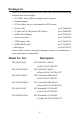
Packing List Before you begin installing your card, please make sure that the following materials have been shipped: • 1 PCI-6881 Series Half-sized single board computer • 1 Startup manual • 1 CD for utility, drivers, and manual (in PDF format) • 1 Power cable p/n:1700000265 • 1 Y cable for PS/2 Keyboard, PS/2 Mouse p/n:1700060202 • 1 FDD cable (600mm) p/n:1701340603 • 1 Printer port cable p/n:1700260250 • 1 ATX feature cable p/n:1700001276 • 1 EIDE (HDD) cable p/n:1701400452 • Mini Jumper p/n:
Additional Information and Assistance Visit the Advantech website at www.advantech.com where you can find the latest information about the product. Step 1. Contact your distributor, sales representative, or Advantech's customer service center for technical support if you need additional assistance.
FCC This device complies with the requirements in part 15 of the FCC rules: Operation is subject to the following two conditions: 1.This device may not cause harmful interference, and 2. This device must accept any interference received, including interference that may cause undesired operation This equipment has been tested and found to comply with the limits for a Class A digital device, pursuant to Part 15 of the FCC Rules.
PCI-6881 User Manual vi
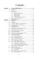
Contents Chapter 1 General Information ........................................2 1.1 1.2 1.3 Introduction ....................................................................... 2 Features ............................................................................. 2 Specifications .................................................................... 3 1.3.1 1.3.2 1.3.3 1.3.4 1.3.5 1.4 Chapter Standard SBC Functions................................................. 3 Display Interface...................
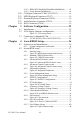
2.19.2 HDD LED (Pin1&Pin2,Pin3&Pin4,Pin5&Pin6) .......... 18 2.19.3 Power Button (Pin9&Pin10)......................................... 18 2.20 2.21 2.22 2.23 2.24 Chapter COM port Connector (CN6,CN12,CN13) ...................... 19 MINI Keyboard Connector (CN17) ................................ 19 External Keyboard Connector (CN18)............................ 19 Audio Interface Connector (CN15)................................. 19 DI/O Connector (CN16)..................................................
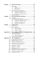
Chapter 5 PCI SVGA Setup ............................................42 5.1 Introduction ..................................................................... 42 5.1.1 5.1.2 5.1.3 5.2 Installation of the SVGA Driver ..................................... 43 5.2.1 5.2.2 5.2.3 5.3 Chapter Installation for Windows 98/ME .................................. 43 Installation for Windows NT ........................................ 47 Installation for Windows 2000/XP ...............................
B.13 B.14 B.15 B.16 B.17 B.18 B.19 B.20 B.21 B.22 COM port 2 (CN13) ........................................................ 92 LVDS Connector (CN14) .......................................... 93 AC’97 Interface Connector (CN15) ............................ 94 DI/O Connector (CN16) ............................................ 94 MINI Keyboard Connector (CN17) ................................ 95 External Keyboard Connector (CN18)......................... 95 LCD Inverter Power Connector (CN19) ..............
CHAPTER 1 General Information This chapter gives background information on the PCI-6881.
Chapter 1 General Information 1.1 Introduction The PCI-6881 series is a half-sized PCI bus CPU card designed with powerful Intel Pentium M or Celeron M processor, with Intel 855GME and ICH4 chipset, which supports enhanced Intel "SpeedStep" technology and Dynamic Video Memory Technology. For maximum performance, PCI-6881 also supports two 200 Pin SODIMM socket and ECC DDR memory up to 2 GB. These chipsets are specifically for embedded computing and provide an optimized on-board integrated graphics solution.
• Supports 400 MHz Front Side Bus • Accepts 128/256/512 bit technologies DDR 200/266/333 DRAM 1.3 Specifications 1.3.1 Standard SBC Functions • CPU: Supports Intel® Embedded Pentium® M (Banias) LV/ULV or Dothan Processor, up to 2.
1.3.3 Solid State disk • Supports CompactFlash Card Type I/II 1.3.4 Ethernet interface • Chipset: Intel 82541PI (Gigabit), Intel 82551ER/82551QM (optional) • Connection: on-board RJ-45 connector • Interface: IEEE 802.3 z/ab (1000Base-T) or IEEE 802.3u (100Base-T) protocol compatible • Built-in Boot ROM: 82541PI and 82551QM (optional) • I/O address switchless setting 1.3.5 Mechanical and Environmental • Dimensions (L x W): 185 x 122 mm (7.3” x 4.
1.4 Board layout: dimensions 185.00 10.91 90.93 100.70 4.00 59.26 31.45 87.30 4.01 6.03 15.12 39.15 23.62 93.62 121.92 25.35 93.24 43.61 9.59 8.34 7.33 4.33 15.06 22.32 2.53 104.47 Figure 1.1: Board layout: dimensions (component side) 41.20 45.50 76.42 Figure 1.
PCI-6881 User Manual 6
CHAPTER 2 Installation This chapter explains the setup procedures of PCI-6881 hardware, including instructions on setting jumpers and connecting peripherals, switches and indicators. Be sure to read all safety precautions before you begin the installation procedure.
Chapter 2 Installation 2.1 Jumpers The PCI-6881 has a number of jumpers that allow you to configure your system to suit your application. The table below lists the functions of the various jumpers. Table 2.
2.2 Connectors Onboard connectors link the PCI-6881 to external devices such as hard disk drives, a keyboard, or floppy drives. The table below lists the function of each of the board’s connectors. Table 2.
2.3 Locating Connectors (component side) CN2 CN3 CN6 CN4 CN7 CN8 CN9 CN1 CN5 FAN1 CN10 JP1 DIMM1 CN11 JP2 CN12 DIMM2 CN13 CN15 CN21 CN17 CN18 JP3 JP4 CN22 CN16 CN14 CN19 Figure 2.1: Jumper & Connector Locations 2.4 Locating Connectors (solder side) CN20 Figure 2.
2.5 Setting Jumpers You may configure your card to match the needs of your application by setting jumpers. A jumper is a metal bridge used to close an electric circuit. It consists of two metal pins and a small metal clip (often protected by a plastic cover) that slides over the pins to connect them. To “close” a jumper, you connect the pins with the clip. To “open” a jumper, you remove the clip. Sometimes a jumper will have three pins, labeled 1, 2 and 3.
2.6 Clear CMOS (JP1) Warning! To avoid damaging the computer, always turn off the power supply before setting “Clear CMOS.” Before turning on the power supply, set the jumper back to “3.0 V Battery On.” This jumper is used to erase CMOS data and reset system BIOS information. The procedure for clearing CMOS is: 1. Turn off the system. 2. Short pin 1 and pin 2. 3. Turn on the system. The BIOS is now reset to its default setting Table 2.
2.7 COM2 RS-232/422/485 Select (JP2) Table 2.4: COM2 RS-232/422/485 Select 1-2 (default) RS-232 3-4 RS-422 5-6 RS-485 2.8 PCI_VIO Power Select (JP3) 1 2 3 1 2 3 Table 2.5: PCI_VIO Power Select Pin Function 1-2 (default) +5 V 2-3 +3.3 V 2.9 LVDS Panel Power Select (JP4) 1 2 3 1 2 3 Table 2.6: LVDS Panel Power Select Pin Function 1-2 (default) +5 V 2-3 +3.
2.10 Installing SODIMMs Notes The modules can only fit into a socket one way. The gold pins must point down into the SODIMM socket. The procedure for installing SODIMMs appears below. Please follow these steps carefully. 1. Make sure that all power supplies to the system are switched off 2. Install the SODIMM card. Install the SODIMM so that its gold pins point down into the SODIMM socket. 3.
2.12 Printer port Connector (CN3) Normally, the printer port is used to connect the card to a printer. The PCI-6881 includes a multi-mode (SPP/EPP/ECP) printer port accessed via CN3 and a 26-pin flat-cable connector. You will need an adapter cable if you use a traditional DB-25 connector. The adapter cable has a 26-pin connector on one end, and a DB-25 connector on the other. The printer port is designated as LPT1, and can be disabled or changed to LPT2 or LPT3 in the system BIOS setup.
3. If you are connecting a 5.25” floppy drive, line up the slot in the printed circuit board with the blocked-off part of the cable connector. If you are connecting a 3.5” floppy drive, you may have trouble determining which pin is number one. Look for a number printed on the circuit board indicating pin number one. In addition, the connector on the floppy drive may have a slot. When the slot is up, pin number one should be on the right.
2.16 VGA/LVDS interface connections The PCI-6881’s display interface can drive conventional CRT displays and is capable of driving a wide range of LVDS flat panel displays as well. The board has two display connectors: one for standard CRT VGA monitors, and one for LVDS flat panel displays. 2.16.1 CRT display Connector (CN10) CN10 is a standard 15-pin D-SUB connector used for conventional CRT displays.
CSMA/CD standards. It is supported by all major network operating systems. The PCI-6881 supports 10/100Base-T or 1000Base-T Ethernet connections with onboard RJ-45 connectors (CN11). PCI-6881F series supports 10/100Base-T LAN, PCI-6881FG series supports 1000Base-T LAN. 2.18.1 LAN Connector (CN11) 10/100Base-T or 1000Base-T connects to the PCI-6881 via a cable to a standard RJ-45 connector. 2.18.
2.20 COM port Connector (CN6,CN12,CN13) The PCI-6881 provides four COM ports (COM1,COM3,COM4: RS-232 and COM2: RS-232/422/485). CN12 supports COM1, CN13 supports COM2, CN6 supports COM3, COM4. And JP2 is for COM2 RS-232/ 422/485 selection. It provides connections for serial devices (a mouse, etc.) or a communication network. You can find the pin assignments for the COM port connector in Appendix B. 2.
PCI-6881 User Manual 20
CHAPTER 3 Software Configuration This chapter details the software configuration information. It shows you how to configure the card to match your application requirements. Award System BIOS will be covered in Chapter 4.
Chapter 3 Software Configuration 3.1 Introduction The system BIOS and custom drivers are located in a 512 KB, 32-pin (JEDEC spec.) Flash ROM device, designated U15. A single Flash chip holds the system BIOS, VGA BIOS, and network Boot ROM image. The display can be configured via software. This method minimizes the number of chips and eases configuration. You can change the display BIOS simply by reprogramming the Flash chip. 3.
2. At the prompt, type AWDFLASH.EXE and press . The VGA configuration program will then display the following: Figure 3.1: VGA setup screen 3. At the prompt, enter the new BIN file which supports your display. When you are sure that you have entered the file name correctly press . 4. The screen will ask “do you want to save the BIOS?” If you change your mind or have made a mistake, press N to abort and end the setup procedure.
3.3.1 AU M170EG01(1280 x1024 LVDS LCD) Table 3.
CHAPTER 4 Chapter 4 Ducks that Need Love! Award BIOS Setup This chapter describes how to set BIOS configuration data.
Chapter 4 Award BIOS Setup 4.1 System test and initialization These routines test and initialize board hardware. If the routines encounter an error during the tests, you will either hear a few short beeps or see an error message on the screen. There are two kinds of errors: fatal and non-fatal. The system can usually continue the boot up sequence with non-fatal errors.
4.2 Award BIOS setup Award’s BIOS ROM has a built-in Setup program that allows users to modify the basic system configuration. This type of information is stored in battery-backed CMOS RAM so that it retains the Setup information when the power is turned off. 4.2.1 Entering setup Power on the computer and press immediately. This will allow you to enter Setup. Figure 4.
4.2.2 Standard CMOS Features setup When you choose the Standard CMOS Features option from the Initial Setup Screen menu, the screen shown below is displayed. This standard Setup Menu allows users to configure system components such as date, time, hard disk drive, floppy drive and display. Once a field is highlighted, on-line help information is displayed in the left bottom of the Menu screen. Figure 4.
4.2.3 Advanced BIOS Features setup By choosing the Advanced BIOS Features Setup option from the Initial Setup Screen menu, the screen below is displayed. This sample screen contains the manufacturer’s default values for the PCI-6881 Series. Figure 4.
4.2.4 Advanced Chipset Features setup By choosing the Advanced Chipset Features option from the Initial Setup Screen menu, the screen below is displayed. This sample screen contains the manufacturer’s default values for the PCI-6881 Series. Figure 4.
4.2.5 Integrated Peripherals Choosing the Integrated Peripherals option from the Initial Setup Screen menu should produce the screen below. Here we see the manufacturer’s default values for the PCI-6881 Series. Figure 4.
4.2.6 Power Management Setup By choosing the Power Management Setup option from the Initial Setup Screen menu, the screen below is displayed. This sample screen contains the manufacturer’s default values for the PCI-6881 Series. Figure 4.
4.2.7 PnP/PCI Configurations By choosing the PnP/PCI Configurations option from the Initial Setup Screen menu, the screen below is displayed. This sample screen contains the manufacturer’s default values for the PCI-6881 Series. Figure 4.
4.2.8 PC Health Status The PC Health Status option displays information such as CPU and motherboard temperatures, fan speeds, and core voltage. Figure 4.
4.2.9 Frequency/Voltage Control By choosing the Frequency/Voltage Control option from the Initial Setup Screen menu, the screen below is displayed. This sample screen contains the manufacturer’s default values for the PCI-6881. Figure 4.9: Frequency/Voltage Control Caution Incorrect settings in Frequency/Voltage Control may damage the system CPU, video adapter, or other hardware.
4.2.10 Load Optimized Defaults Load Optimized Defaults loads the default system values directly from ROM. If the stored record created by the Setup program should ever become corrupted (and therefore unusable), these defaults will load automatically when you turn the PCI-6881 Series system on. Figure 4.10: Load BIOS defaults screen 4.2.
To Establish Password 1. Choose the Set Password option from the CMOS Setup Utility main menu and press . 2. When you see “Enter Password,” enter the desired password and press . 3. At the “Confirm Password” prompt, retype the desired password, then press . 4. Select Save to CMOS and EXIT, type , then . Figure 4.11: Set password To Change Password 1. Choose the Set Password option from the CMOS Setup Utility main menu and press . 2.
4. Select Set Password again, and at the “Enter Password” prompt, enter the new password and press . 5. At the “Confirm Password” prompt, retype the new password, and press . 6. Select Save to CMOS and EXIT, type , then . To Disable Password 1. Choose the Set Password option from the CMOS Setup Utility main menu and press . 2. When you see “Enter Password,” enter the existing password and press . 3. You will see “Confirm Password.
4.2.12 Save & Exit Setup Figure 4.12: Save to CMOS and EXIT If you select this option and press then , the values entered in the setup utilities will be recorded in the chipset’s CMOS memory. The microprocessor will check this every time you turn your system on and use the settings to configure the system. This record is required for the system to operate.
4.2.13 Exit Without Saving Figure 4.13: Quit without saving Selecting this option and pressing lets you exit the Setup program without recording any new values or changing old ones.
CHAPTER 5 PCI SVGA Setup Introduction Installation of SVGA drivers -for Windows 95/98/Me -for Windows NT/2000/XP Further information
Chapter 5 PCI SVGA Setup 5.1 Introduction The board has an onboard interface. The specifications and features are described as follows: 5.1.1 Chipset The PCI-6881 uses a Intel 855GME + ICH4 chipset for its graphic controller. It supports LVDS LCD displays, conventional CRT monitors. 5.1.2 Display memory The 855GME chip with optimized Shared Memory Architecture, supports up to 32 MB frame buffer using system memory to provide LVDS mode up to 1280 x 1024 @ 36bpp with frequency range from 25 MHz to 112 MHz.
5.2 Installation of the SVGA Driver Complete the following steps to install the SVGA driver. Follow the procedures in the flow chart that apply to the operating system that you are using within your board. Notes: 1. The windows illustrations in this chapter are intended as examples only. Please follow the listed steps, and pay attention to the instructions which appear on your screen. 2. For convenience, the CD-ROM drive is designated as "D" throughout this chapter. 5.2.
2. Press the "Next" button 3.
4.
5.
5.2.2 Installation for Windows NT Note: Service Pack X (X = 3, 4, 5, 6,...) must be installed first, before you install the Windows NT VGA driver. To install SVGA driver for Window NT, please run the setup wizard "Intel Extreme Graphic 2" in CD-ROM. Example of installation is shown as bellow: 1. Select the path: D:\2_VGA, then double click "winnt41361" to run "Install Shield Wizard", and press “Next” button.
2.
3. In order to install Intel® Extreme Graphics 2, you must accept the agreement, press the "Yes" button and wait a minute.
4. Choose the option "Yes, I want to restart my computer now", then press the "Finish" button. 5.2.3 Installation for Windows 2000/XP To install SVGA driver for Window 2000/XP, please run the setup wizard "Intel Extreme Graphic 2" in CD-ROM.
1. Select the path: W:\2_VGA, then double click "win2k_xp149" to run "Install Shield Wizard" 2. Press the "Next" button.
3. Press the "Next" button.
4. In order to continue setup, you must accept the agreement, press the "Yes" button and wait a minute.
5. Choose the option "Yes, I want to restart my computer now." and press the "Finish" button. 5.3 Further Information For further information about the AGP/VGA installation in your PCA6881, including driver updates, troubleshooting guides and FAQ lists, visit the following web resources: VIA website: www.via.com.tw Advantech websites: www.advantech.com www.advantech.com.
CHAPTER 6 PCI Bus Ethernet Interface This chapter provides information on Ethernet configuration.
Chapter 6 PCI Bus Ethernet Interface 6.1 Introduction The board is equipped with a high performance 32-bit Ethernet chipset which is fully compliant with 802.3u 100Base-T or 802.3z/ab 1000BaseT. It is supported by major network operating systems. It is also both 100Base-T and 10Base-T compatible. The Ethernet port provides a standard RJ-45 jack. The network boot feature can be utilized by incorporating the boot ROM image files for the appropriate network operating system.
1. a. Select "Start", "Settings". "Control Panel". b. Double click "Network". 2. a. Click "Add" and prepare to install network functions.
3. a. Select the "Adapter" item to add the Ethernet card. 4. a. Click "Have Disk" to install the driver.
5. a. Insert the CD into the D: drive b. Fill in "D:\3_lan\82551ER\W9xW2k” c. Click "OK" 6. a. Choose the " Intel 8255x based PCI Ethernet Adapter (10/100)" b. Click "OK".
7. a. Make sure the configurations of relative items are set correctly. b. Click "Yes" to reboot. 6.2.3 Installation for Windows XP 1. Please wait for a moment.
2.
6.2.4 Installation for Windows NT 1. a. Select "Start", "Settings", "Control Panel" b.
2. Click “Add”. 3. Click “Have Disk.
4. a. Insert the Utility CD ROM b. Fill in the correct path: E:\3_lan\82551ER\WinNT c. Click "OK". 5. Check the highlighted item, and click “OK.
6. Click “Yes”.
7. a. Choose Adapter option "[1] Intel® GD82559ER Evaluation Adapter" b.
8. Click "Apply" 9. Click “Yes” to reboot your computer.
PCI-6881 User Manual 68
CHAPTER 7 Audio Setup • Introduction • Installation of audio driver for Windows 98 • Installation of audio driver for Windows XP 69 Chapter 7
Chapter 7 Audio Setup 7.1 Introduction The PCI-6881 supports AC97 audio through the optional audio module PCM-231A-00A1. Notes The audio function needs external AUDIO board e.g. PCM-231. 7.2 Driver installation 7.2.1 Before you begin Please read the instructions in this chapter carefully before you attempt installation. The audio drivers for the PCI-6881 board are located on the audio driver CD. Run the supplied SETUP program to install the drivers; don't copy the files manually.
7.2.2 Windows 98 driver 1. Press the "OK" button 2.
7.2.3 Windows XP driver To install audio driver for Window XP, please run the setup wizard in CDROM. Example of installation is shown as bellow: 1. Select the path: D:\wdm_a357, then double click to run "Install Shield Wizard" 2.
3. Choose the option "Yes, I want to restart my computer now", then click "Finish" button to reboot your computer.
PCI-6881 User Manual 74
Appendix A Programming GPIO & Watchdog Timer The board is equipped with a watchdog timer that resets the CPU or generates an interrupt if processing comes to a standstill for any reason. This feature ensures system reliability in industrial standalone or unmanned environments.
Appendix A Programming GPIO & Watchdog Timer A.1 Supported GPIO Register Below are detailed description of the GPIO addresses and programming sample. A.1.1 GPIO Registers CRF0 (GP10-GP17 I/O selection register. Default 0xFF) When set to a '1', respective GPIO port is programmed as an input port. When set to a '0', respective GPIO port is programmed as an output port. CRF1 (GP10-GP17 data register. Default 0x00) If a port is programmed to be an output port, then its respective bit can be read/written.
A.1.2 GPIO Example program-1 -----------------------------------------------Enter the extended function mode, interruptible double-write -----------------------------------------------MOV DX,2EH MOV AL,87H OUT DX,AL OUT DX,AL --------------------------------------------------------------Configure logical device 7(GP10~GP17), configuration register CRF0,CRF1,CRF2 --------------------------------------------------------------MOV DX,2EH MOV AL,07H ; point to Logical Device Number Reg.
OUT DX,AL MOV DX,2FH MOV AL,??H ; Put the output value into AL OUT DX,AL -----------------------------------------Exit extended function mode | -----------------------------------------MOV DX,2EH MOV AL,AAH OUT DX,AL A.
Outportb (0x4e,0x77); Outportb (0x4e,0x77); //Entry Configuration Mode Outportb (0x4e,0x07); //Select Register Index 0x07 Outportb (0x4f,0x08); //Select LDN 8 Outportb (0x4e,0x30); //Select LDN 8 Register Index 0x30 Outportb (0x4f,0x00); //Disable Watchdog Timer Device Outportb (0x4e,0xaa); //Exit Configuration Mode 79 Appendix A
PCI-6881 User Manual 80
Appendix B Pin Assignments This appendix contains information of a detailed or specialized nature.
Appendix B Pin Assignments B.1 Primary IDE Connector (CN1) Table B.
B.2 Floppy Connector (CN2) Table B.2: Floppy Connector (CN2) Pin Signal Pin Signal 1 GND 2 RWC# 3 GND 4 NC 5 GND 6 DS 7 GND 8 Index# 9 GND 10 MOA# 11 GND 12 DSB# 13 GND 14 DSA# 14 GND 16 MOB# 17 GND 18 DIR# 19 GND 20 STEP# 21 GND 22 WD# 23 GND 24 WE# 25 GND 26 Track0# 27 GND 28 WP# 29 GND 30 RDATA# 31 GND 32 HEAD# 33 GND 34 DSKCHG# *low active 83 Appx.
B.3 Printer Port Connector (CN3) Table B.
B.4 Secondary IDE Connector (CN4) Table B.
B.5 ATX Power Connector (CN5) Table B.
B.6 COM port 3, 4 (CN6) Table B.6: COM port 3,4 (CN6) Pin Signal Pin Signal 1 DCD3 2 DSR3 3 SIN3 4 RTS3 5 SOUT3 6 CTS3 7 DTR3 8 RI3 9 GND 10 GND 11 DCD4 12 DSR4 13 SIN4 14 RTS4 15 SOUT4 16 CTS4 17 DTR4 18 RI4 19 GND 20 GND B.7 USB port 1, 2 (CN7) Table B.7: USB port 1, 2 (CN7) Pin Signal Pin Signal 1 +5V 2 +5V 3 USB0- 4 USB1- 5 USB0+ 6 USB1+ 7 USB GND 8 USB GND 9 GND 10 NC 87 Appx.
B.8 USB port 3, 4 (CN8) Table B.8: USB port 3, 4 (CN8) Pin Signal Pin Signal 1 +5V 2 +5V 3 USB0- 4 USB1- 5 USB0+ 6 USB1+ 7 USB GND 8 USB GND 9 GND 10 NC B.9 HDD LED/Reset/Power Button (CN9) 2 4 1 6 8 10 3 5 7 9 Table B.
B.10 D-SUB VGA Connector (CN10) 5 1 10 6 15 11 Table B.10: D-SUB VGA Connector (CN10) Pin Signal Pin Signal 1 R 9 +5V 2 G 10 GND 3 B 11 NC 4 NC 12 S-DATA 5 GND 13 HSYNC 6 GND 14 VSYNC 7 GND 15 S-CLK 8 GND 89 Appx.
B.11 LAN RJ45 Connector (CN11) 8 6 4 2 7 5 3 1 Table B.
B.12 COM port 1 (CN12) 9 8 7 6 5 4 3 2 1 Table B.12: COM port 1 (CN12) Pin Signal 1 DCD 2 SIN 3 SOUT 4 DTR 5 GND 6 DSR 7 RTS 8 CTS 9 RI 91 Appx.
B.13 COM port 2 (CN13) Table B.
B.14 LVDS Connector (CN14) Table B.14: LVDS Connector (CN14) Pin Signal Pin Signal 1 +5V/3.3V 2 +5V/3.3V 3 GND 4 GND 5 +5V/3.3V 6 +5V/3.
B.15 AC’97 Interface Connector (CN15) Table B.15: AC’97 Interface Connector (CN15) Pin Signal Pin Signal 1 +5V 2 BitCLK 3 DATA IN 4 GND 5 GND 6 Sync 7 DATA OUT 8 ACRST 9 +5V 10 NC B.16 DI/O Connector (CN16) Table B.
B.17 MINI Keyboard Connector (CN17) 6 4 2 5 3 1 Table B.17: MINI Keyboard Connector (CN17) Pin Signal 1 KBDATA 2 MSDATA 3 GND 4 +5V 5 KBCLK 6 MSCLK B.18 External Keyboard Connector (CN18) Table B.18: External Keyboard Connector (CN18) Pin Signal 1 KBCLK 2 KBDATA 3 NC 4 GND 5 +5V 95 Appx.
B.19 LCD Inverter Power Connector (CN19) Table B.
B.20 CompactFlash Connector (CN20) Table B.
B.21 ATX Feature Connector (CN21) 1 2 3 Table B.21: ATX Feature Connector (CN21) Pin Signal 1 VCCSB 2 GND 3 PS_ON# B.22 -12V Power Connector (CN22) 1 2 3 Table B.
Appendix C System Assignments This appendix contains information of a detailed nature. It includes: • • • • System I/O ports 1st MB memory map DMA channel assignments Interrupt assignments 99 Appx.
Appendix C System Assignments C.1 System I/O Ports Table C.1: System I/O ports Addr.
Table C.1: System I/O ports Addr. range (Hex) Device 778-77A Printer Port (ECP Extensions)(Port 378+400) MPU-401 select from 300 ~ 330H (2 bytes) C.2 1st MB memory map Table C.2: 1st MB memory map Addr.
C.3 DMA channel assignments Table C.
C.4 Interrupt assignments Table C.
PCI-6881 User Manual 104
Appendix D SpeedStep Technology 105 Appx.
Appendix D SpeedStep Technology D.1 Intel® Pentium® M SpeedStep instruction Mobile Intel® Pentium® M processors with Enhanced Intel SpeedStep® technology let users customize high performance computing on their PC.The Enhanced Intel SpeedStep technology provides the Pentium M processor a flexible, multi-point operating mode, completely self managed, and with a very low CPU and memory unavailability time, which optimizes its power and performance according to demand.
Step 2. Change “Power schemes" to "Portable/Laptop” 107 Appx.
Step 3. Discover the different CPU freq.
The Result of Pentium M speed stepping: 1.1 G---600 MHz / 800 MHz / 1.1 GHz (Intel® Pentium® M) 1.6 G---600 MHz / 800 MHz / 1.0 GHz /1.2 GHz / 1.4 GHz / 1.6 GHz (Intel® Pentium® M) 109 Appx.
PCI-6881 User Manual 110