
User manual


v Table of Contents
Contents
Chapter 1 General Information ....................................... 2
1.1 Introduction ................................................................................. 2
1.2 Features........................................................................................ 2
1.3 Applications................................................................................. 3
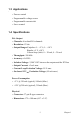
1.4 Specifications............................................................................... 3
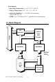
1.5 Block Diagram............................................................................. 4
Chapter 2 Installation ....................................................... 6
2.1 Unpacking.................................................................................... 6
2.2 Driver Installation........................................................................ 7
Figure 2.1: Setup Screen of Advantech Automation Software 7
Figure 2.2: Different Options for Driver Setup ........................ 8
2.3 Hardware Installation .................................................................. 9
Figure 2.3: The Device Name Listed on Device Manager .... 10
2.4 Device Setup and Configuration ............................................... 11
2.4.1 Setting Up the Device ............................................................. 11
Figure 2.4: The Device Manager Dialog Box ........................ 11
2.4.2 Configuring the Device .......................................................... 12
Figure 2.5: The Device Setting dialog box ............................ 12
Figure 2.6: Device Name Appearing on List of Devices Box 13
Chapter 3 Jumpers and I/O Connectors ....................... 16
Figure 3.1: Jumper Locations (SW1 is only for PCI-1720U) 16
3.1 Jumper Settings.......................................................................... 16
3.1.1 Using Jumpers to Set Current Sink Ranges ............................ 16
Figure 3.2: Jumper Settings for PCI-1720U’s Current Sink
Range ................................................................... 16
3.1.2 Jumper JP5 Setting for the Reset State ................................... 17
Figure 3.3: Jumper JP5 Setting for the Reset State ................ 17
3.2 Connector and Pin Assignments................................................ 18
Figure 3.4: PCI-1720U Pin Assignments ............................... 18
3.2.1 Signal Descriptions of I/O Connector .................................... 19
3.3 Setting the BoardID Switch (SW1) ........................................... 20
Table 3.1: Board ID Setting (SW1) ...................................... 20
3.3.1 Identity Register ..................................................................... 21