PCI-1713 32-ch Isolated Analog Input Card User Manual
Copyright The documentation and the software included with this product are copyrighted 2006 by Advantech Co., Ltd. All rights are reserved. Advantech Co., Ltd. reserves the right to make improvements in the products described in this manual at any time without notice. No part of this manual may be reproduced, copied, translated or transmitted in any form or by any means without the prior written permission of Advantech Co., Ltd. Information provided in this manual is intended to be accurate and reliable.
Product Warranty (2 years) Advantech warrants to you, the original purchaser, that each of its products will be free from defects in materials and workmanship for two years from the date of purchase. This warranty does not apply to any products which have been repaired or altered by persons other than repair personnel authorized by Advantech, or which have been subject to misuse, abuse, accident or improper installation.
Declaration of Conformity CE This product has passed the CE test for environmental specifications when shielded cables are used for external wiring. We recommend the use of shielded cables. This kind of cable is available from Advantech. Please contact your local supplier for ordering information. Technical Support and Assistance Step 1. Visit the Advantech web site at www.advantech.com/support where you can find the latest information about the product. Step 2.
Safety Instructions 1. Read these safety instructions carefully. 2. Keep this User's Manual for later reference. 3. Disconnect this equipment from any AC outlet before cleaning. Use a damp cloth. Do not use liquid or spray detergents for cleaning. 4. For plug-in equipment, the power outlet socket must be located near the equipment and must be easily accessible. 5. Keep this equipment away from humidity. 6. Put this equipment on a reliable surface during installation.
20° C (-4° F) OR ABOVE 60° C (140° F). THIS COULD DAMAGE THE EQUIPMENT. THE EQUIPMENT SHOULD BE IN A CONTROLLED ENVIRONMENT. 16. CAUTION: DANGER OF EXPLOSION IF BATTERY IS INCORRECTLY REPLACED. REPLACE ONLY WITH THE SAME OR EQUIVALENT TYPE RECOMMENDED BY THE MANUFACTURER, DISCARD USED BATTERIES ACCORDING TO THE MANUFACTURER'S INSTRUCTIONS. The sound pressure level at the operator's position according to IEC 7041:1982 is no more than 70 dB (A).
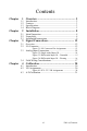
Contents Chapter 1 Overview .......................................................... 2 1.1 1.2 1.3 1.4 Chapter 2 Installation ....................................................... 8 2.1 2.2 2.3 Chapter Chapter Introduction ....................................................................... 2 Features ............................................................................. 3 Specifications .................................................................... 3 Block Diagram ................
PCI-1713 User Manual viii
CHAPTER 1 2 Overview Sections include: • Introduction • Features • Specifications • Block Diagram
Chapter 1 Overview 1.1 Introduction The PCI-1713 is a 12-bit 32-channel analog input card for the PCI bus. It provides 32 analog input channels with a sampling rate up to 100k samples/s, 12-bit resolution and isolation protection of 2500 VDC. PCI-bus Plug and Play The PCI-1713 uses a PCI controller to interface the card with the PCI bus. The controller fully implements the PCI bus specification Rev 2.1.
Satisfies the Need for Isolation Protection The PCI-1713 provides optical isolation protection of 2500 VDC between the inputs and the PC bus to protect the PC and peripherals from damage due to high voltages on the input lines. It is ideal for the situations where budget-conscious users require flexibility, stability and a high level of isolation protection for their data acquisition system. 1.
• Accuracy: (depending on gain) Gain Accuracy 0.5, 1 0.01% of FSR±1LSB 2 0.02% of FSR±1LSB 4 0.02% of FSR±1LSB 8 0.04% of FSR±1LSB • Linearity error: ±1 LSB • Drift: Typical 30 PPM / °C ( 0 ~ 60 °C ) • Input impedance: 1 GW • Trigger mode: Software, on-board programmable pacer or external • Trigger Input: TTL level Programmable Timer/Counter • Counter chip: 82C54 or equivalent • Counters: 3 channels, 16 bits 2 channels are permanently configured as programmable pacers; 1 channel is un-used.
1.
PCI-1713 User Manual 6
CHAPTER 2 2 Installation Sections include: • Initial Inspection • Unpacking • Installation Instructions
Chapter 2 Installation 2.1 Initial Inspection Before installing the PCI-1713, check the card for visible damage. We have carefully inspected the card both mechanically and electrically before shipment. It should be free of marks and in perfect order upon receipt. As you unpack the PCI-1713, check it for signs of shipping damage (damaged box, scratches, dents, etc.). If it is damaged or fails to meet specifications, notify our service department or your local sales representative immediately.
2.3 Installation Instructions The PCI-1713 can be installed in any PCI slot in the computer. However, refer to the computer user's manual to avoid any mistakes and danger before you follow the installation procedure below: 1. Turn off your computer and any accessories connected to the computer. Warning!TURN OFF your computer power supply whenever you install or remove any card, or connect and disconnect cables. 2. Disconnect the power cord /other cables from the back of the computer. 3.
PCI-1713 User Manual 10
CHAPTER 3 2 Signal Connections Sections include: • Overview • I/O Connector • Analog Input Connections • Field Wiring Considerations
Chapter 3 Signal Connections 3.1 Overview Correct signal connections are one of the most important factors in ensuring that your application system is sending and receiving data correctly. A good signal connection can avoid much unnecessary and costly damage to your valuable PC and other hardware devices. This chapter will provide some useful information about how to connect analog input signals to the PCI-1713 card via the I/O connector. 3.
Figure 3.
I/O Connector Signal Descriptions A/D code Mapping Voltage Hex. Dec. Bipolar ±5V Unipolar 0 to 10V 000h 0 -4.9971V 0V 7FFh 2047 -0.0024V 4.9947V 800h 2048 0V 4.9971V FFFh 4095 +4.9947V 9.9918V 3.3 Analog Input Connections This section continues to describe how to make analog input signal connections to the PCI-1713 card via the I/O connector.
Differential Channel Connections The differential input configuration has two signal wires for each channel, and the differential input responds only to voltage differences between High and Low inputs. On the PCI-1713 card, when all channels are configured to differential input, up to 16 analog channels are available. Internal External AI0 AI2 Multiplexer + PGIA Measured Voltage GroundReferenced Signal Source AI30 AI1 _ AI3 Multiplexer AI31 GND I/O Connector Figure 3.3: Differential Input Ch.
Figure 3.4: Differential Input Ch. - Floating If a floating signal source is connected to the differential input channel, the signal source may exceed the common-mode signal range of the PGIA, and the PGIA will be saturated with erroneous voltage-readings. You must therefore reference the signal source to the AIGND. Figure 3-4 shows a differential channel connection between a floating signal source and an input channel on the PCI-1713 card.
External Trigger Source Connection In addition to pacer triggering, the PCI-1713 card also allows external triggering for A/D conversions. A low-to-high edge coming from EXT_TRG will trigger an A/D conversion on the PCI-1713 board. Note!:Don't connect any signal to the EXT_TRG pin when the external trigger function is not being used.
PCI-1713 User Manual 18
CHAPTER 4 2 Calibration Sections include: • Introduction • VR Assignments • A/D Calibration
Chapter 4 Calibration 4.1 Introduction Regular calibration checks are important to maintain accuracy in data acquisition and control applications. To assist users in the A/D calibration process, we provide the Advantech Device Manager, on the PCI1713 software CD-ROM. The Advantech Device Manager makes A/D calibrations easy. It leads you through the calibration and setup procedure with a variety of prompts and graphic displays, showing you all of the correct settings and adjustments.
The following list shows the function of each VR: VR Function VR1 A/D full scale (gain) VR2 A/D bipolar offset VR3 A/D unipolar offset VR4 PGIA initial offset TP1 PGIA output 4.3 A/D Calibration 1. Connect Pin1 to Pin9 and measure the output as "V1" from TP1.
2. Adjust VR4 until | V1 – V2 | < 0.05mV. For example, if the V1 is 0.1mV in the beginning and you get V2 as 0.02mV after adjusting the VR4, you have to adjust the VR4 again. 3. Input -5V to AI0 by signal generator and check if the "Decimal" flickers between 0 and 1. For example, it is 3 for my calibration, so I have to adjust the VR2.
4. Input 5V to AI0 by signal generator and check if the "Decimal" flickers between 4094 and 4095. 5. Input 5V to AI1 by signal generator and check if the "Decimal" flickers between 2047 and 2048. Calibration finished.
A/D code Mapping Voltage Hex. Dec. Bipolar ±5V Unipolar 0 to 10V 000h 0 -4.9971V 0V 7FFh 2047 -0.0024V 4.9947V 800h 2048 0V 4.9971V FFFh 4095 +4.9947V 9.