
Specifications


Appendix C
– 81 – PCI-1710 series User’s Manual
Advantech Co., Ltd.
www.advantech.com
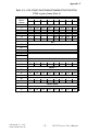
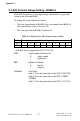
C.6 MUX Control - BASE+4 and BASE+5
Table C-8: Register for multiplexer control
STA3 ~ STA0 Start Scan Channel Number
STO3 ~ STO0 Stop Scan Channel Number
• When you set the gain code of analog input channel n, you should
set the Multiplexer start & stop channel number to channel n to
prevent any unexpected errors. In fact BASE+4 bit 3 to bit 0, STA3
~ STA0, act as a pointer to channel n’s address in the SRAM when
you program the A/D channel setting (refer to Section C.5).
Caution!
✎ We recommend you to set the same start and stop channel when
writing to the register BASE+2. Otherwise, if the A/D trigger source is
on, the multiplexer will continuously scan between channels and the
range setting may be set to an unexpected channel. Make sure the A/D
trigger source is turned off to avoid this kind of error.
The write-only registers of BASE +4 and BASE+5 control how the
multiplexers (Multiplexer) scan.
• BASE+4 bit 3 to bit 0, STA3 ~ STA0, hold the start scan channel
number.
• BASE+5 bit 3 to bit 0, STO3 ~ STO0, hold the stop scan channel
number.
Writing to these two registers automatically initializes the scan range
of the Multiplexer. Each A/D conversion trigger also sets the Multi-
plexer to the next channel. With continuous triggering, the Multiplexer
will scan from the start channel to the stop channel and then repeat.
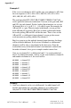
The following examples show the scan sequences of the Multiplexer.
Example 1
If the start scan input channel is AI3 and the stop scan input channel
is AI7, then the scan sequence is AI3, AI4, AI5, AI6, AI7, AI3, AI4,
AI5, AI6, AI7, AI3, AI4...
Write Multiplexer Control
Bit # 7 6 5 4 3 2 1 0
BASE + 5 STO3 STO2 STO1 STO0
BASE + 4 STA3 STA2 STA1 STA0